Article / Power electronics · High voltage
5 Apr 2021
Introduction to Tesla coils
A Tesla coil is a resonant air-core transformer. This is the long way around: what resonance actually does, why a spark gap starts one, and why a transistor bridge has to be told the frequency.
What a Tesla coil is
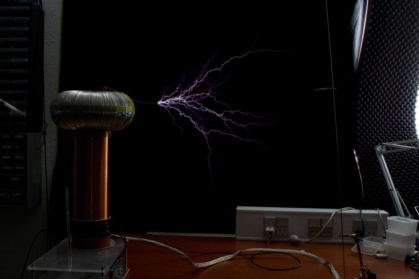
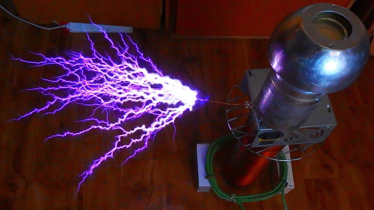
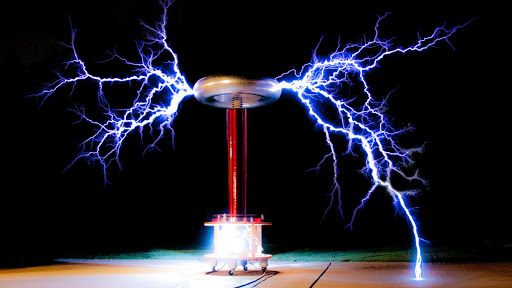
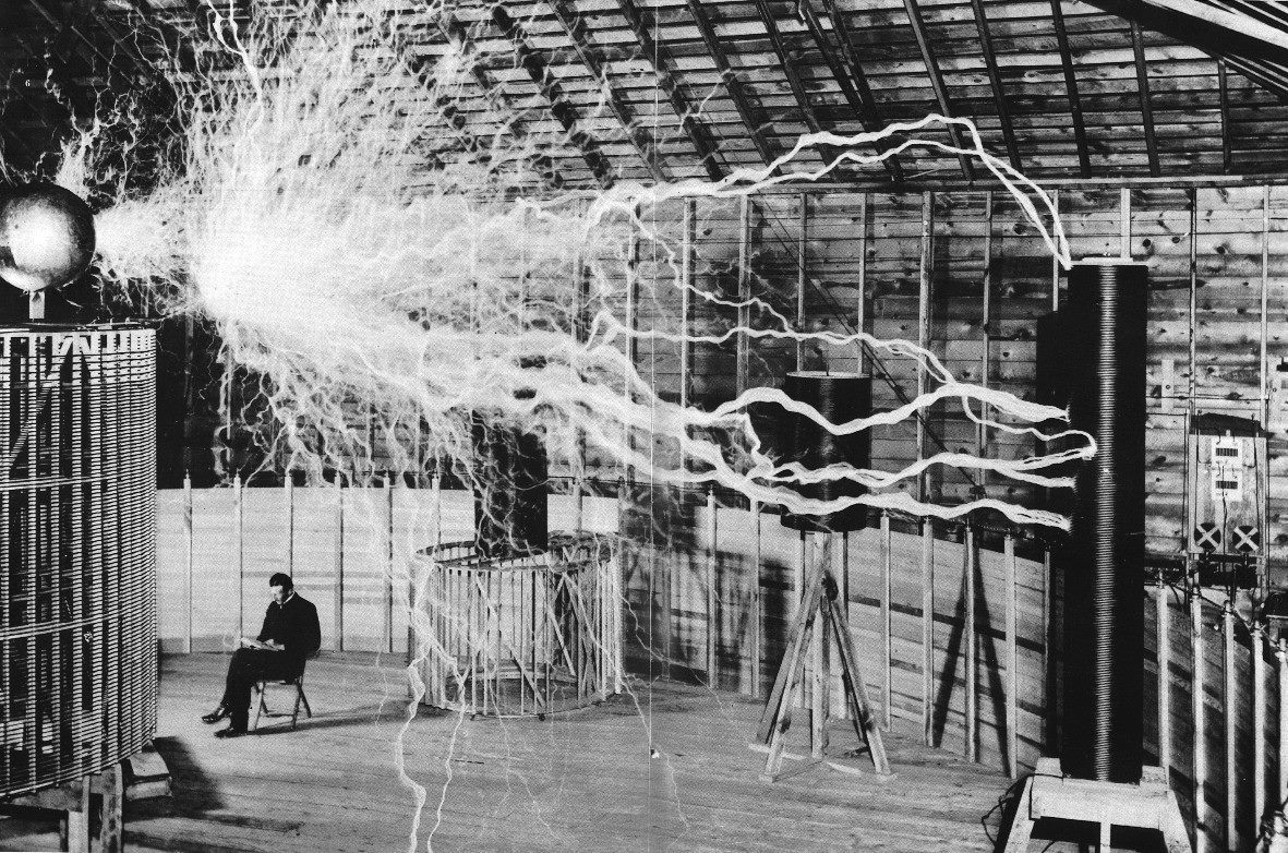
A Tesla coil is a resonant amplifier built around an air-core transformer. It steps the input up by orders of magnitude, until the charge on the secondary repels itself hard enough to ionise the air. That is the arc.
The secondary is the part you cannot miss: thousands of turns, standing in the open. The primary is a few turns, often fewer than ten, and easy to overlook. The whole machine is a transformer. We still call it a coil, because the secondary is what you see.
What Tesla was actually building
A lot of the Tesla folklore is nonsense. He did not have a free-energy machine, and he did not have a death ray that could erase a city on another continent. He did extraordinary work in electromagnetism — AC motors, practical power distribution — and he also spent years on wireless power. The machine we call a Tesla coil was that attempt.
Long-distance power from one of these is not a matter of building it bigger. The field falls off quickly as you walk away, and it is not aimed: it leaves in every direction. The sun has the same problem from our point of view. We catch a tiny fraction of what it radiates. A coil, even with modern switches, would be a terrible way to deliver watts across a field. Tesla kept at it at Wardenclyffe anyway. When that failed, the money stopped. He later sold the military on death rays, weapons and energy harvesters, was funded again, and spent that money on the same wireless-power work. The authorities eventually noticed, and the work was confiscated.
The idea was not useless. You cannot ship power this way. You can ship information. The first spark-gap radio transmitters were Tesla coils with a job, and a phone still moves energy through the air, just in a beam we bothered to aim and modulate.
Resonance is everywhere
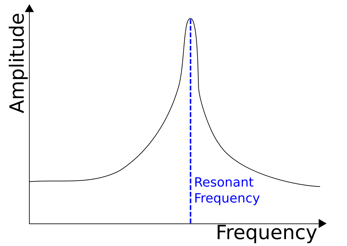
Resonance is a system answering much harder when you drive it at one particular frequency. That frequency is the resonant frequency, the natural frequency, the fundamental.
Most real objects have more than one. They also answer at multiples of the first. The graph is the simple case: a sharp peak, and not much anywhere else.
A string, then a piano
Pluck a guitar string and it rings at its natural frequency. Press the string and you shorten L, so the note goes up. A guitar has strings of equal length that still play different notes, because the speed in the string depends on mass and tension, not only on length.
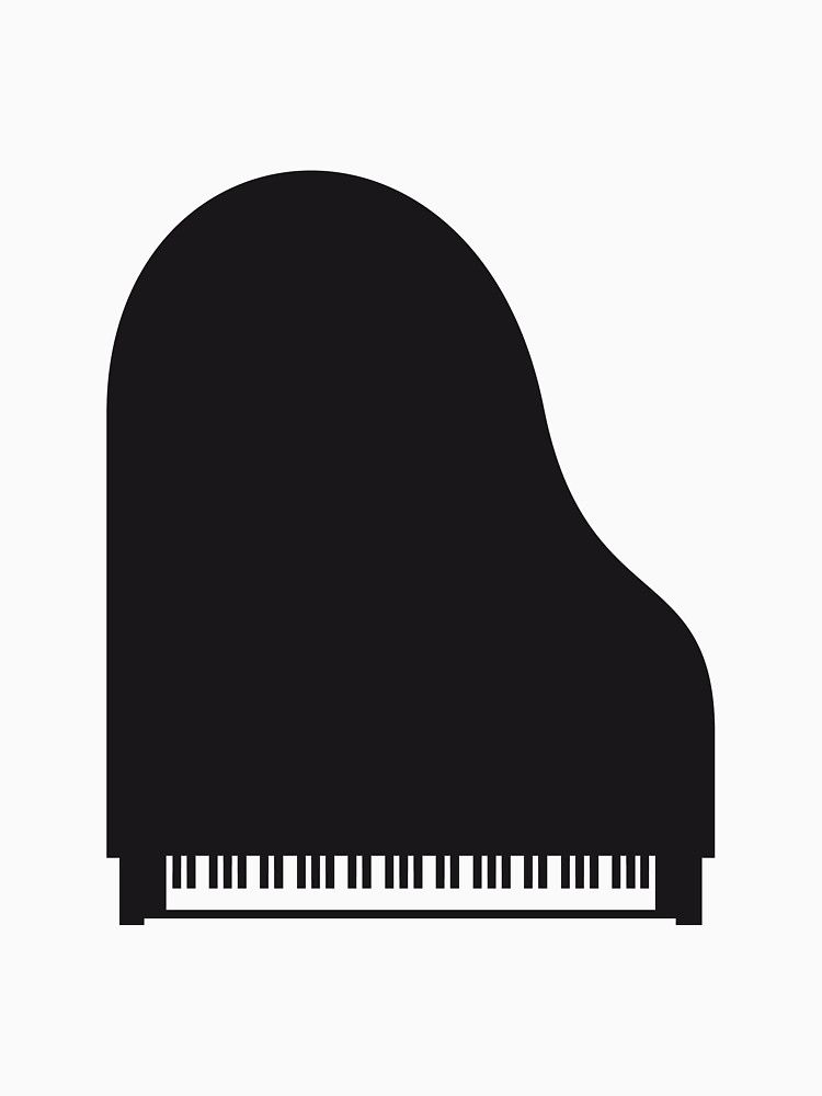
A piano is the same idea built into the furniture. The long side is the bass. The short side is the treble. Higher notes need shorter strings, so the case follows the strings.
f0 = v / (2 L)
More than one fundamental
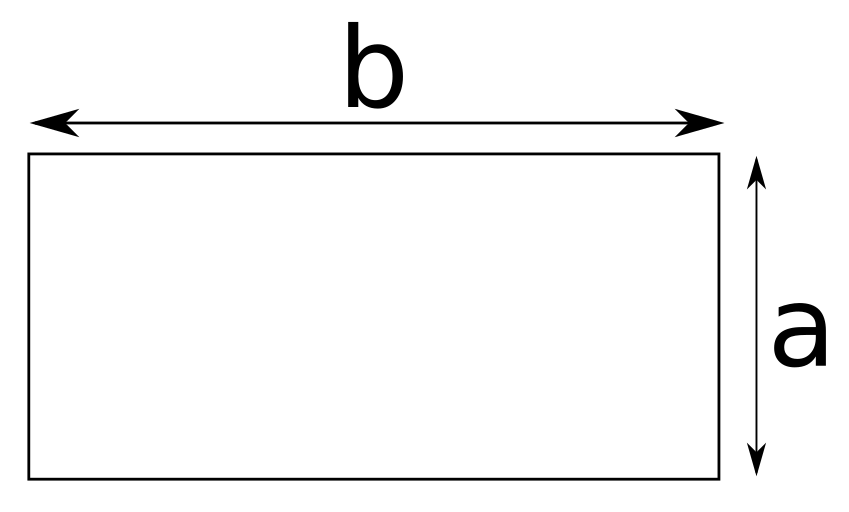
A string has a length, and it also has a width. Hit it along the long side and you hear v / (2 b). Hit it along the short side and you hear v / (2 a). A real pluck does both, plus every other mode the object will support. Most of those sit above what an ear can use. Hearing runs, roughly, from 20 Hz to 20 kHz.
Nothing in the shop is a perfect rectangle. Every scratch and every taper is another place a mode can live. That is why a finished assembly sometimes sings at a frequency the first-pass calculation never had.
When the peak is the failure
Tacoma Narrows was finished in 1940 and stood for about four months. The wind drove the deck at its natural frequency. On a breezy day it moved. In November the wind was fast enough that the motion ran away and the bridge came down. There is a film of the collapse. It is worth watching before you decide a resonance “will not get that big”.
In a circuit, the voltage swings
Electrical resonance is not the board shaking. It is voltage and current trading energy. What follows is simplified on purpose. A capacitor refuses a sudden change in voltage. An inductor refuses a sudden change in current. Charge a capacitor and the voltage arrives late. Push current into an inductor and the current arrives late. When either has gone as far as the circuit will let it, we say it is charged.
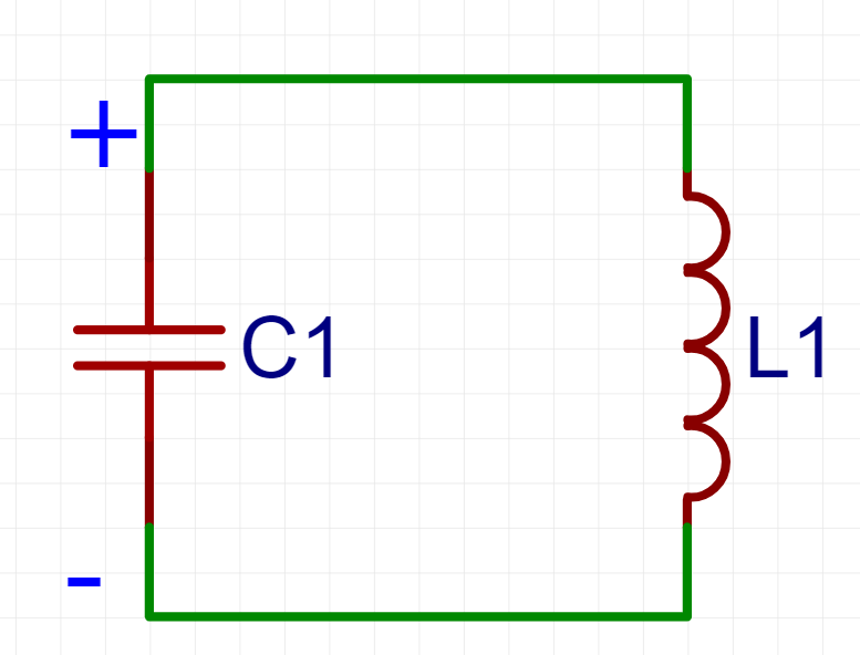
Put only those two parts in a loop and you have an LC circuit. Charge the capacitor, leave the inductor current at zero, and let go.
One cycle
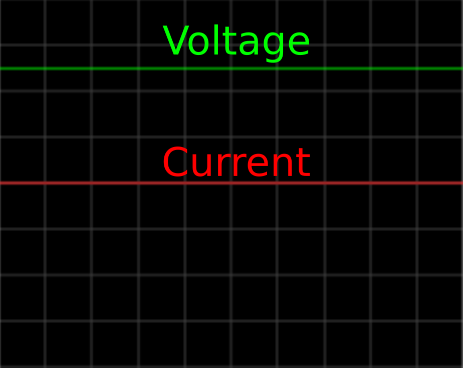
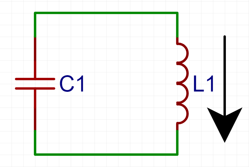
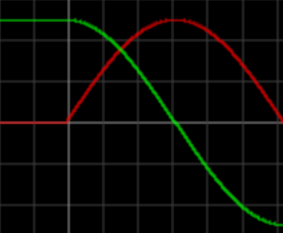
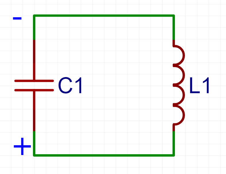
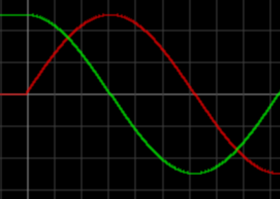
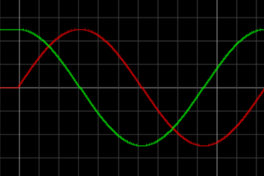
At the start the capacitor sits at full voltage and the inductor current is zero. The capacitor then empties into the inductor. Voltage falls, current rises, until the capacitor is empty and the inductor is carrying the peak current.
The inductor keeps that current moving. It charges the capacitor the other way around: current that left the positive plate comes back onto the negative one, so the voltage reverses. At the far end of that swing the capacitor is full again, in the opposite polarity, and the inductor current is back at zero.
The capacitor now discharges the other way, the inductor charges, and the pair walks back to the polarity they started with. Voltage and current are both sine waves, and the frequency does not wander. It is fixed by L and C. Change either and the note changes. Leave them alone and it does not.
A real loop has resistance. Each cycle turns a little of the stored energy into heat, so the amplitude falls. The frequency stays put. The height does not, unless something keeps feeding the tank.


Two circuits, one frequency
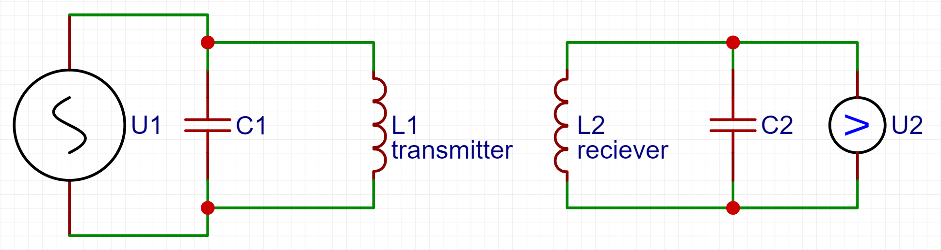
Drive one LC circuit at its resonant frequency and it throws an electromagnetic field. A second LC circuit can catch that field. It catches the most when its own resonant frequency is the same as the transmitter.
Miss the frequency and the transfer collapses. You can be close on a schematic and still move almost no energy. The reason is impedance.
Impedance
Impedance is the opposition a circuit puts up once capacitors and inductors are in it. Reactance is the part that comes from those parts — an AC resistance. Inductive reactance rises with frequency: XL = 2 π f L. At DC an inductor is a short. Take the frequency to infinity and the reactance goes with it. A capacitor does the opposite: XC = 1 / (2 π f C), infinite at DC, smaller as the frequency climbs. The reactance left in the circuit is XL minus XC.
Impedance is that reactance together with the ordinary resistance.
Fix R, L and C, and sweep the source. There is always a frequency where XL equals XC. At that point the reactances cancel, the impedance falls to R, and only the resistance still limits the current. That frequency is the resonant frequency.
f0 = 1 / (2 π √(L · C))
A receiver, with numbers
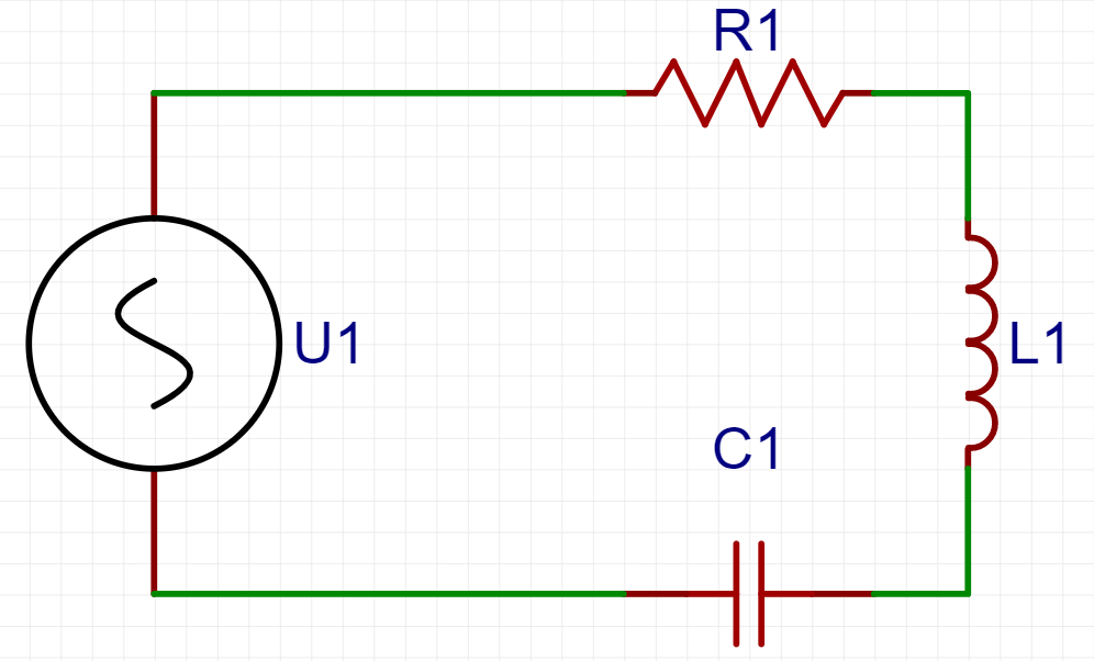
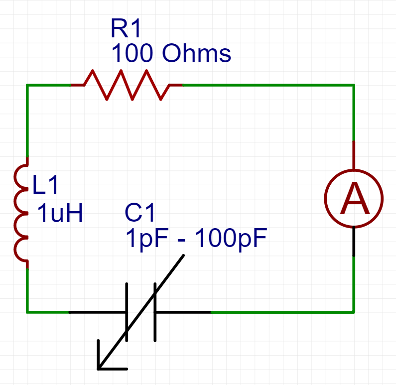
Say the transmitter is on 100 MHz and the receiver should take the largest current it can. A car radio is this circuit: a fixed inductor, a variable capacitor, and you turn the capacitor until a station appears. To make the arithmetic readable, assume the induced voltage stays 1 V at every frequency, and that R1 is the only loss.
Current peaks at resonance, because the reactances cancel and 100 Ω is all that is left. With 1 µH and the capacitor at its stops, this particular part tunes from 15.92 MHz to 159.16 MHz, so 100 MHz is inside the range. Solving for C at 100 MHz gives 2.533 pF. Then I = 1 V / 100 Ω = 10 mA.
Move the capacitor to 3 pF and the tank wants 91.88 MHz. That is 8.2% off 100 MHz, and the current is already down by almost 30%. Twenty percent off cuts it by more than 60%. The example is simplified on purpose. The point survives the simplification: a small tuning error is a large power error.
I = 1 V / 100 Ω = 10 mA
The voltage climbs
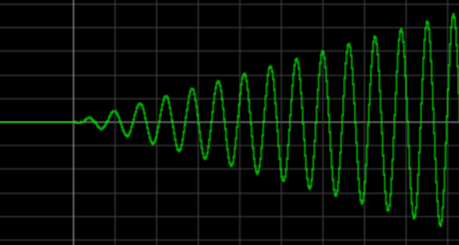
At resonance the energy sits in the oscillation instead of leaving every cycle. Push a little more in and it adds to what is already there. The voltage on the tank can rise above the supply that is feeding it. On a chalkboard with no loss, it rises forever.
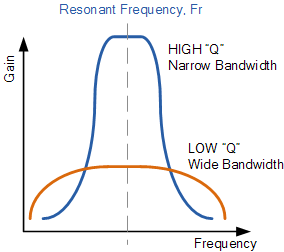
There is always loss, so the amplitude finds a ceiling. The same storage is what pulled the Tacoma deck apart. A high-Q resonance is a tall, narrow peak: more voltage, and a tuning that does not forgive you. A low-Q peak is shorter and wider.
Spark-gap Tesla coil
That is enough theory for the original machine, the spark-gap Tesla coil. An ordinary transformer sets the secondary voltage from the turns ratio alone. A Tesla coil also multiplies by Q, the quality of the resonance. High Q means a higher amplitude and a tuning you have to hit. These are high-Q systems. Once they are on frequency, the secondary can reach hundreds of kilovolts, and on a large coil a few megavolts.
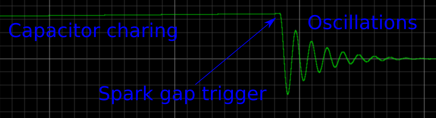
Mains is stepped up, and that high voltage charges the primary capacitor C1. The spark gap is a switch that closes itself: when the voltage breaks down the air between the electrodes, the arc is a hot, low-resistance path, and C1 is dumped into the primary of the resonator. Primary and C1 are the tank. They ring until resistance and the energy handed to the secondary have used up the charge. The primary current in that ring is hundreds of amperes, sometimes thousands. On 50 Hz mains the capacitor is charged twice per cycle, so the bursts come about 100 times a second, either polarity.
Tune the secondary to that same frequency, and give it far more turns than the primary, and the secondary voltage runs away. Match L and C on the two sides and you get the artificial lightning. DiodeGoneWild’s series on a spark-gap coil is the careful version of this explanation: youtube.com/watch?v=wSp1IzmRUk8
U2 = U1 · (N2 / N1) · Q

A gap on a wheel
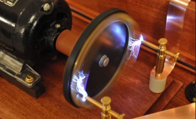
A static gap has ordinary problems. The arc may not quench, the electrodes cook, and the coil does not like to run for long. A rotary spark gap puts the electrodes on a spinning disc. More electrodes share the heat and the wear. The speed sets how often the gap fires. Because the electrodes leave each other, the arc does quench.
Forced quenching has a bill. If you break the arc while the current is still large, that step of current induces a spike in the primary, and the spike lands on the mains transformer. It will kill that transformer. A rotary coil therefore keeps an ordinary safety gap in parallel, to clamp the spike the wheel sometimes makes. This topology is for the high-power spark-gap machines. A fan on the electrodes is part of the design, not a decoration: it cools them and helps the arc die.
Transistors instead of a gap
By the late twentieth century a hobbyist could buy switching transistors. That is where solid-state Tesla coils start. A spark gap will not take orders. The break rate wanders, the bang is loud, and the interference is enough to kill whatever electronics is sitting nearby. The efficiency is often doubtful. A modern build wants the break rate and the power on a knob, and it wants a microcontroller or a logic circuit in charge.
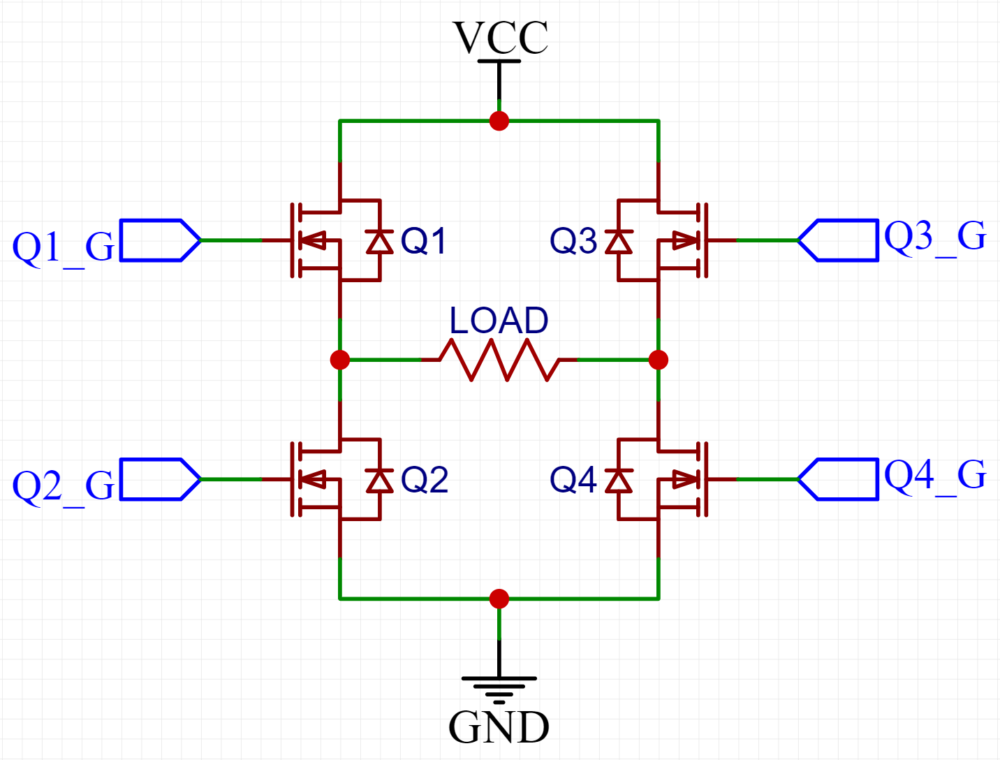
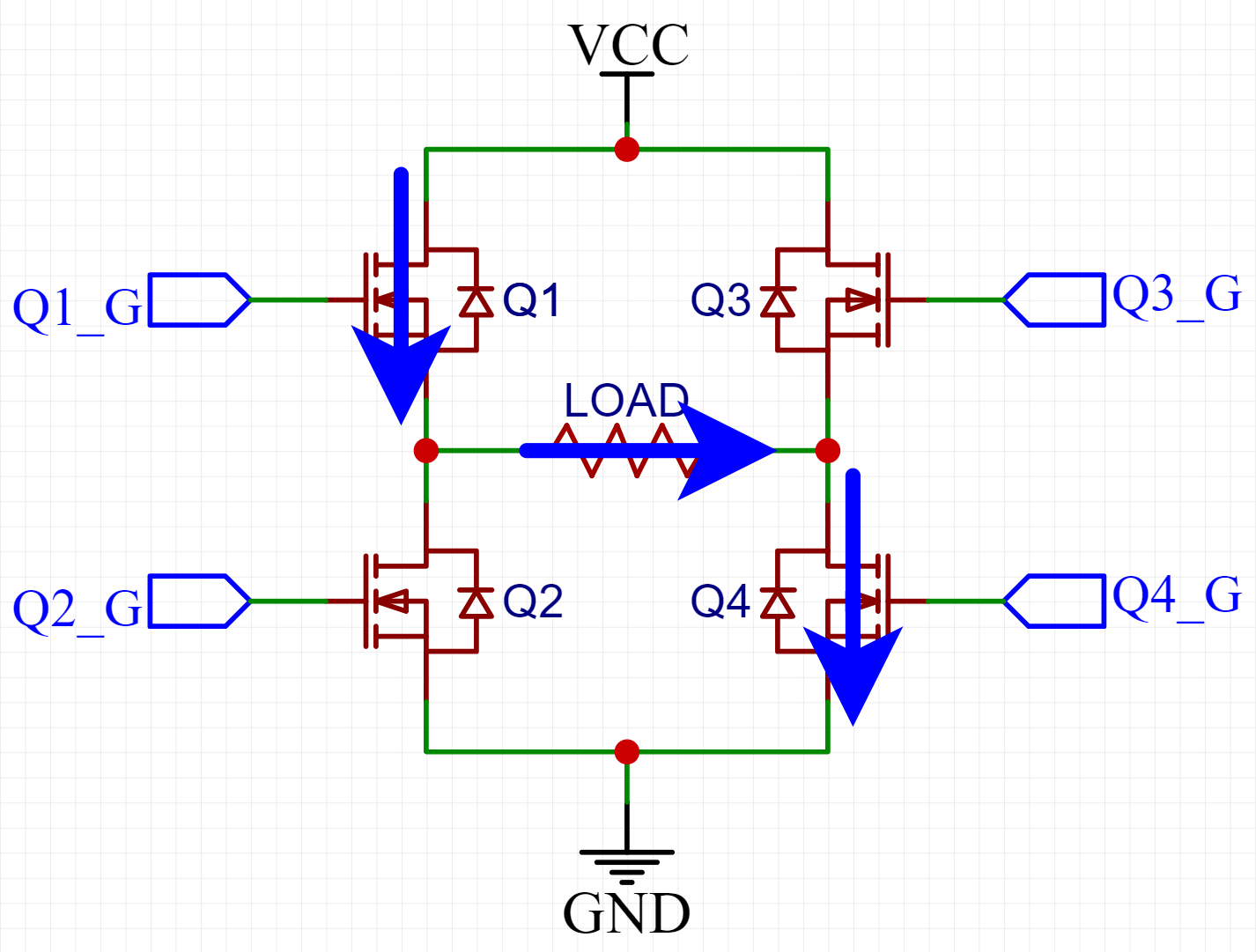
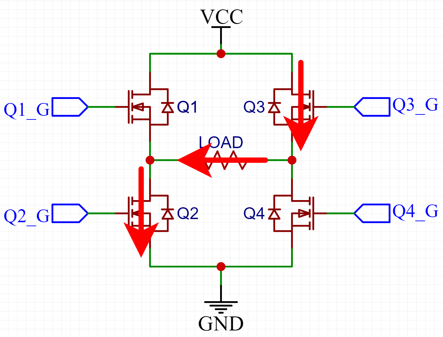
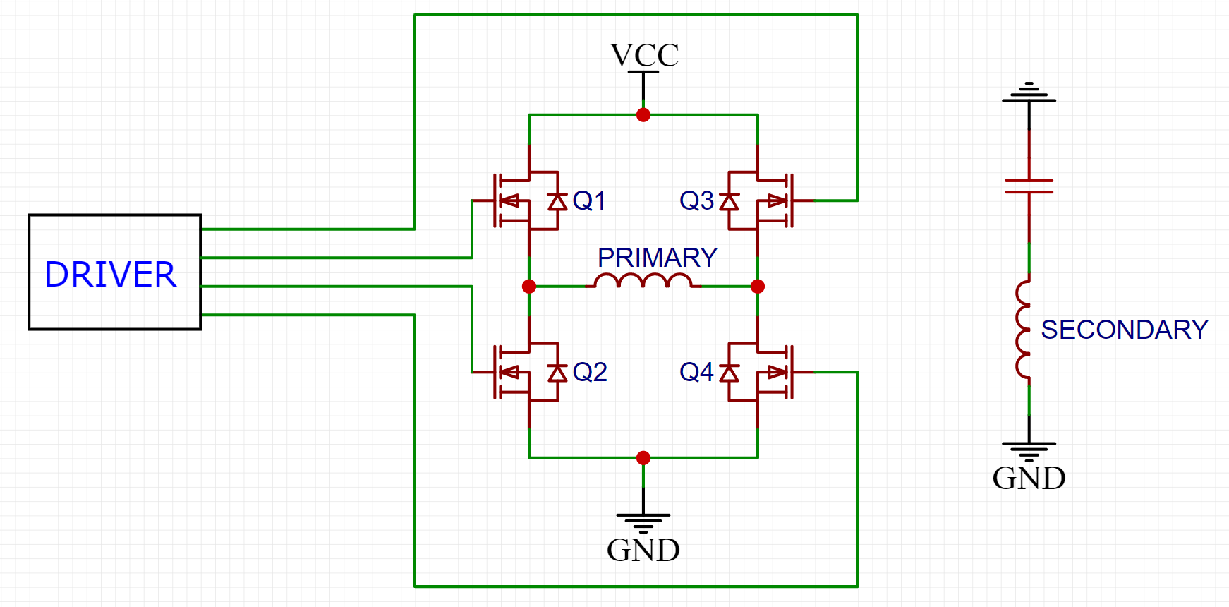
A spark gap lets the primary ring on its own. Transistors have to be driven at the right frequency, and they have to make AC out of DC. One way is an H-bridge, a full bridge. Take rectified mains, about 325 V DC, as Vcc. Turn on Q1 and Q4 together and current goes through the load one way. Turn those off, turn on Q3 and Q2, and the current comes back the other way. Alternate the two pairs and the load sees AC. The gate drive sets the frequency, within what the transistors can actually switch. The result is a square wave made from a DC rail. The same idea, with a transformer primary instead of a resistor, is in everything from a phone charger to a multi-kilowatt server supply.
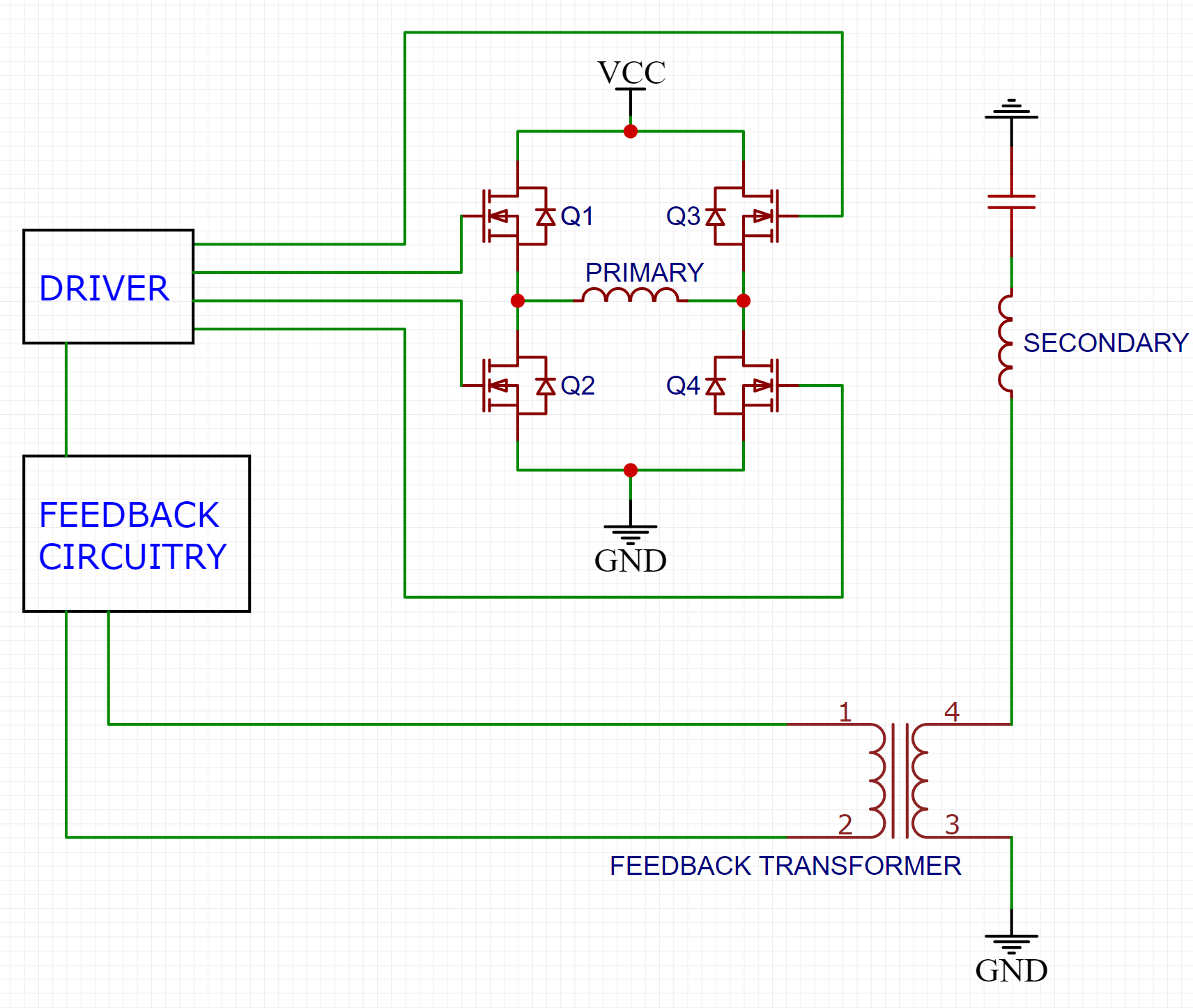
You could measure the secondary once and hard-code that frequency. It works until the room changes. The arc itself is a capacitor hung on the secondary, so a big streamer pulls the resonant frequency down and the driver is suddenly off tune.
Follow the secondary
The usual fix is feedback from the secondary. The bottom of the secondary passes through a ferrite transformer with N turns, a 1:N current transformer, and that signal steers the driver. Draw a heavy arc to ground, shift the secondary by a lot, and the bridge is still on the new frequency. A spark-gap coil cannot do that. Its primary tank is a fixed note.
On an SSTC the primary is not the resonant circuit. Only the secondary is in resonance with the bridge. The primary is an inductance that limits the current, which is why a careful coil can run long pulses, or continuously. You can also wind a low-impedance primary and fire short, violent pulses, the way a spark gap does. The drive is under your control, so the sparks can carry audio: change the break rate and you modulate the power.
Control, paid for in parts
An SSTC is a much larger circuit than a spark gap, and it asks for more electronics than a first coil usually does. A gap is nearly impossible to kill. A transistor dies of overvoltage or of heat without ceremony.
The other side of that bargain is the control. Interrupted, continuous, short high-current pulses, or a coil that plays music. The continuous coil I built, with clean audio on the streamers, is written up separately: uhvlab.org/ctu-sstc
Three coils worth looking at
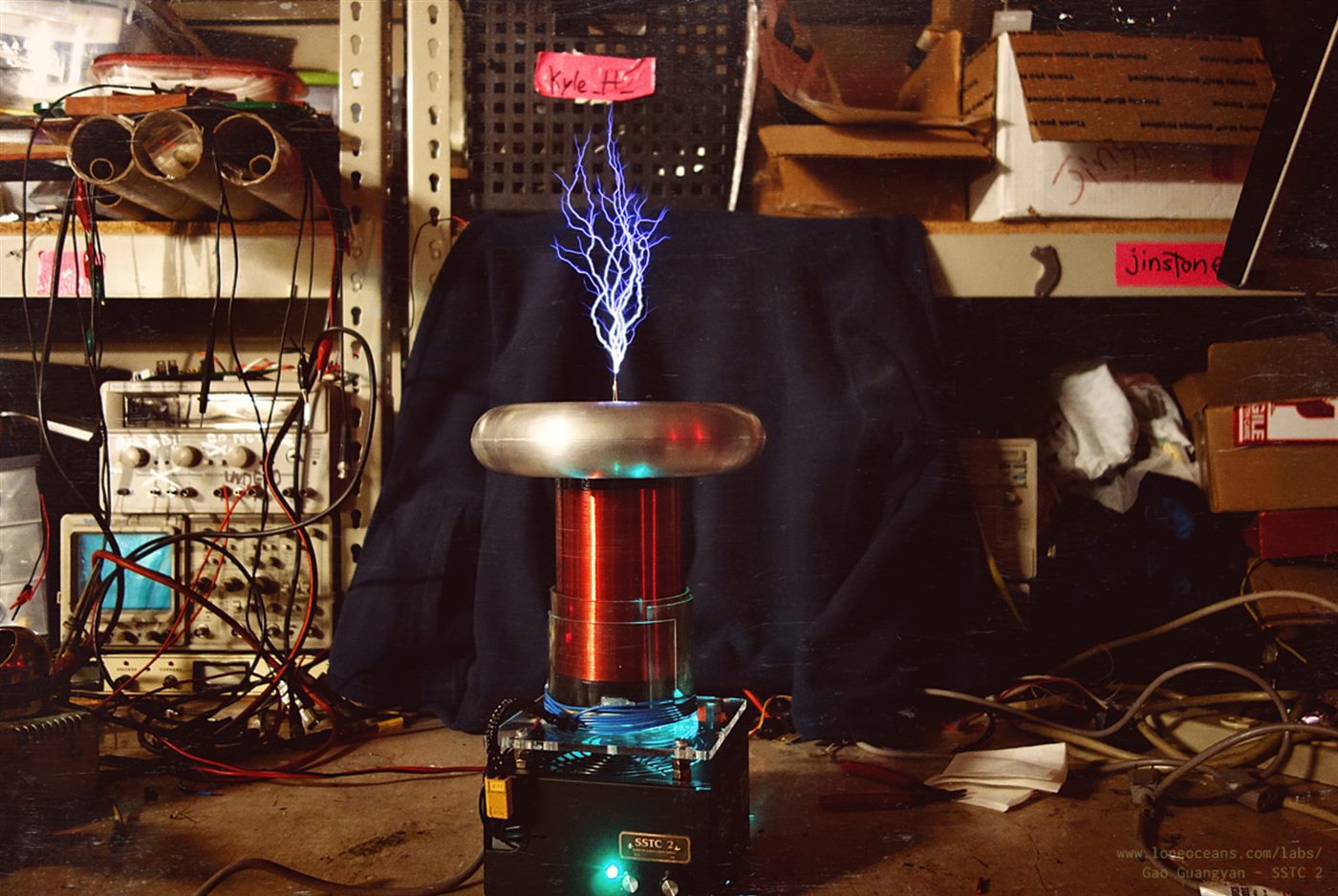
Kaizer’s interrupted SSTC, DiodeGoneWild’s coil running without a feedback loop, and Loneoceans’ interrupted coil. Same idea, three different answers to how hard you drive it and whether you let the secondary talk back.