
Project / Finished product
Constant current load
An adjustable MOSFET load for testing a dual-rail supply. One op-amp, a shunt and a potentiometer hold the current still while the voltage moves.
- Power electronics
- Lab equipment
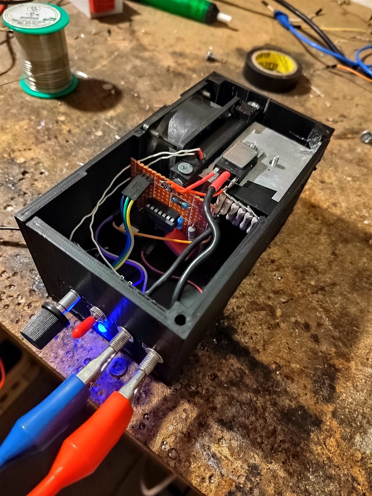
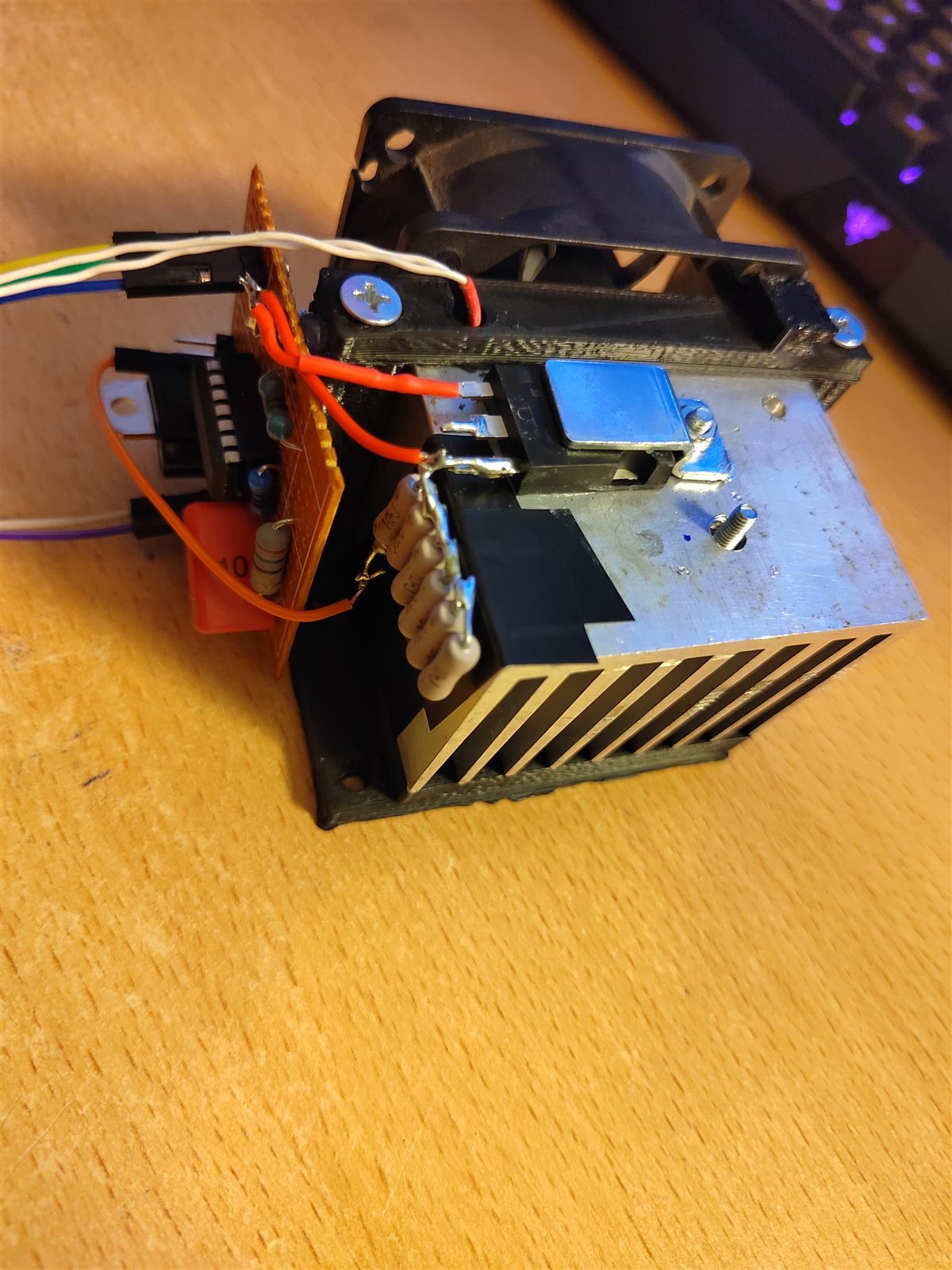
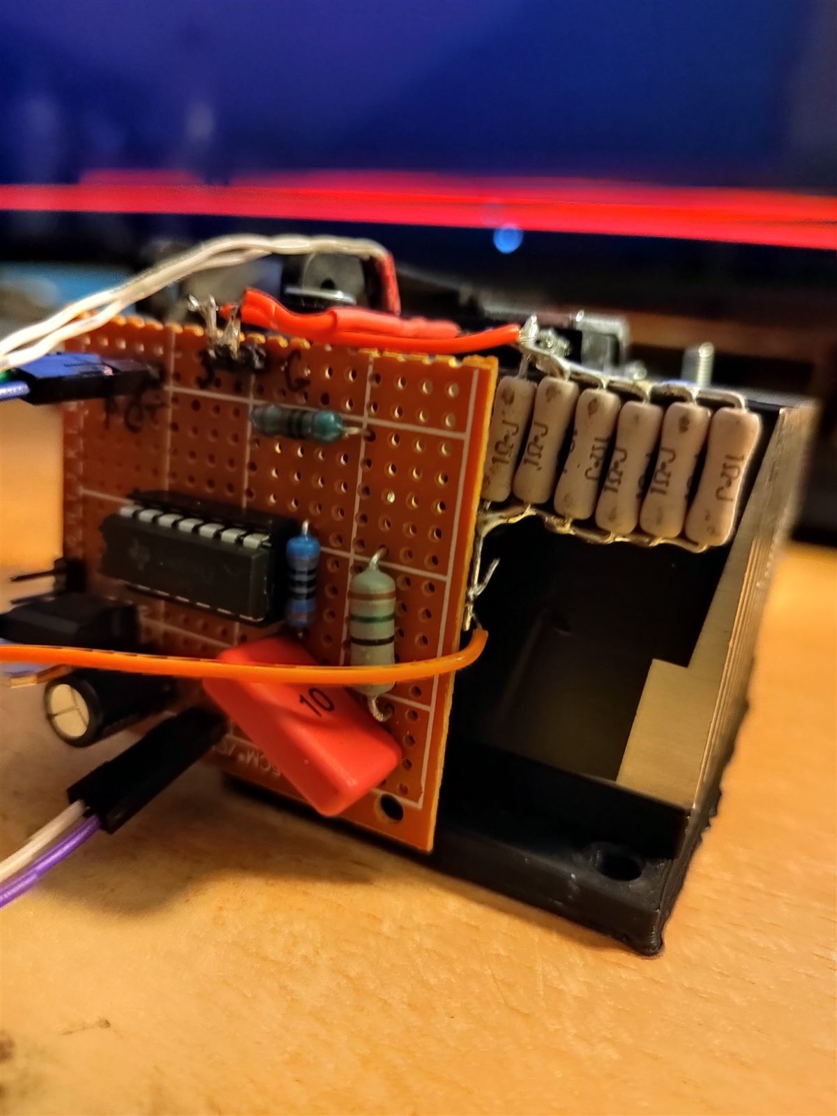
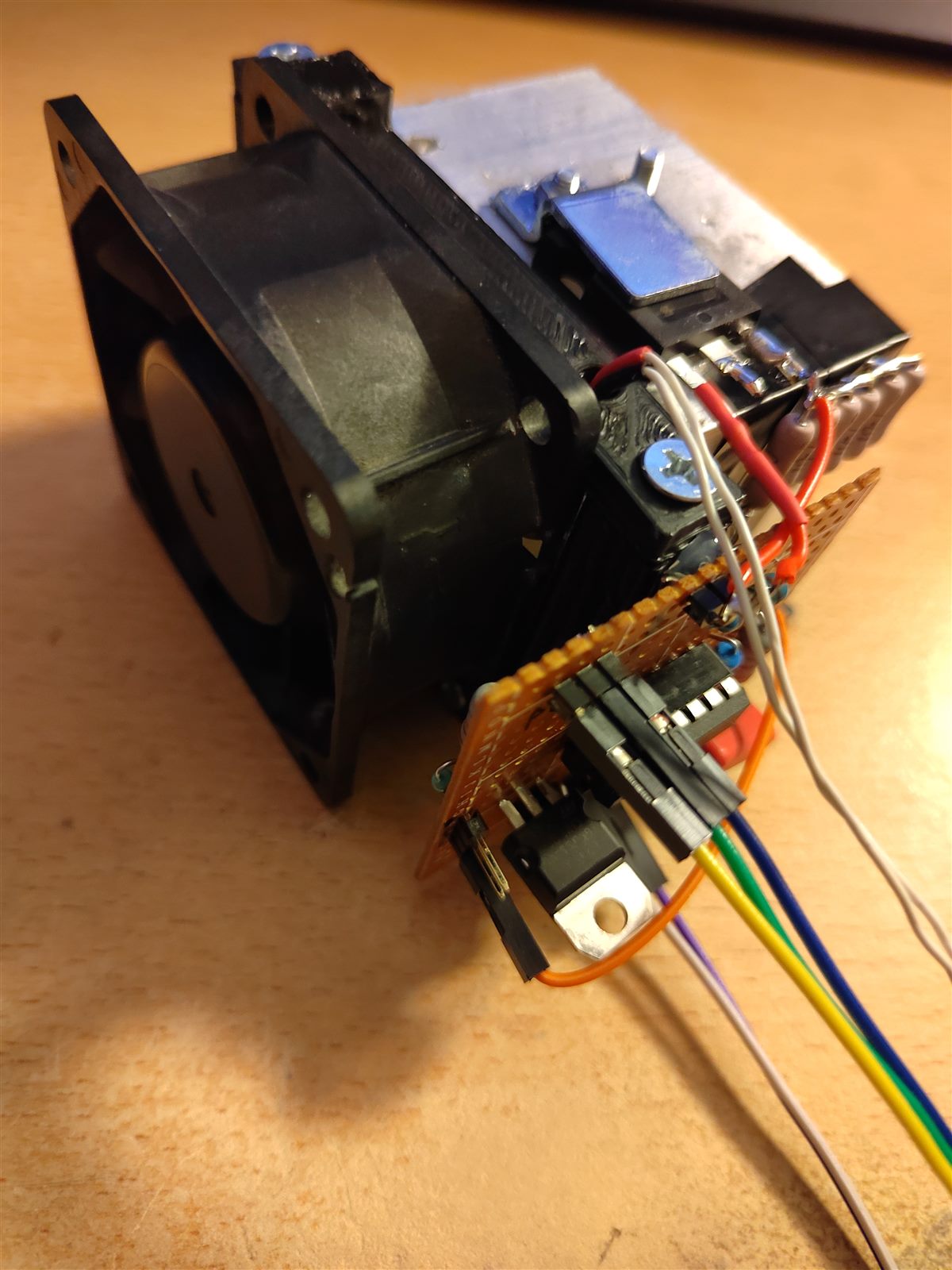
- Status
- Finished product
- Device
- IRFP460
- Range
- 0–9.6 A
- Shunt
- 6 × 1 Ω · 166 mΩ
- Reference
- 5 V · LM317
At a glance
Introduction
I had just built an adjustable dual-rail supply for my bachelor’s thesis, and I needed its efficiency at different output currents. Power resistors would have done it, and they would have been annoying: the current changes with the output voltage, the resistance climbs as they heat, and every new load means picking a new combination and doing the arithmetic again.
A MOSFET makes a much cleaner adjustable load.
How it holds a current
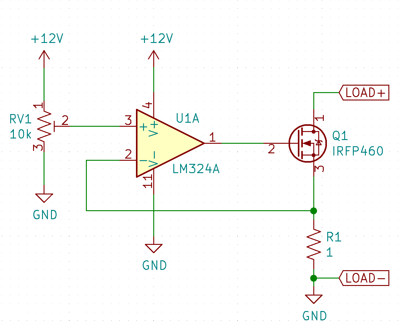
The idea is small. An op-amp drives its output until the voltage between its inputs is zero. Whenever the + input sits above the − input, the output rises, Q1 turns on, and current starts to flow. That current crosses R1, so a voltage appears on the shunt, and that voltage is the feedback into the − input. When the drop matches the + input, the op-amp stops moving and holds the gate there.
The + input is just a potentiometer. Set it so the + input is 2 V and, with a 1 Ω shunt, the op-amp opens the gate until 2 A is flowing. That is the steady state, and it stays there when the supply voltage changes. Any other shunt works the same way. With 1 Ω the ratio is simply one volt per amp.
I = U+ / R
What I actually built
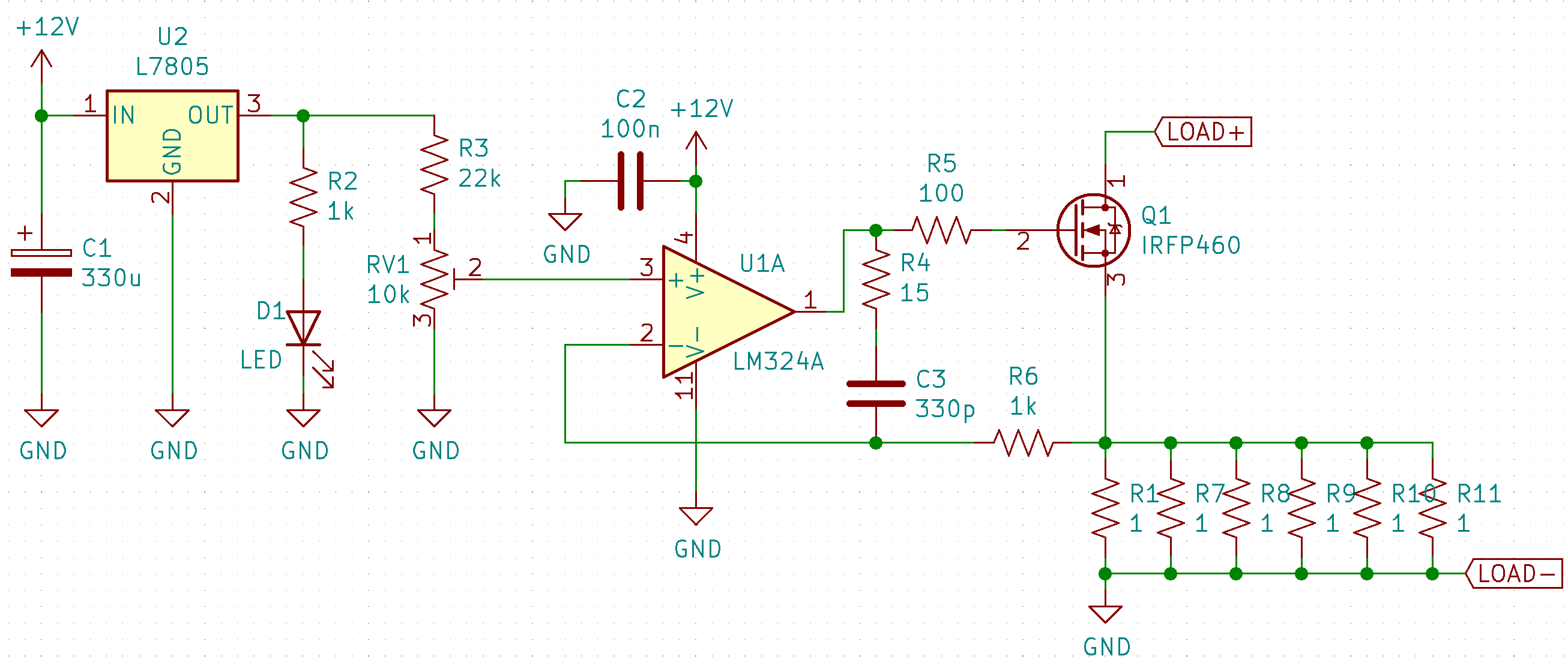
The sketch above is the idea with the parts stripped back. The board follows the second schematic. A linear regulator makes a stable 5 V, and R3 with RV1 divide that 22 kΩ to 10 kΩ, so the highest + input is about 1.6 V. Six 1 Ω resistors in parallel make 166 mΩ. 1.6 V across that shunt is 9.6 A, which is as high as the knob will go.
R5 limits the op-amp current while the IRFP460 gate charges and discharges. R4, R6 and C3 are there for stability. I suspect the loop would have been fine without them.
Imax = 1.6 V / 0.166 Ω ≈ 9.6 A
On the heatsink
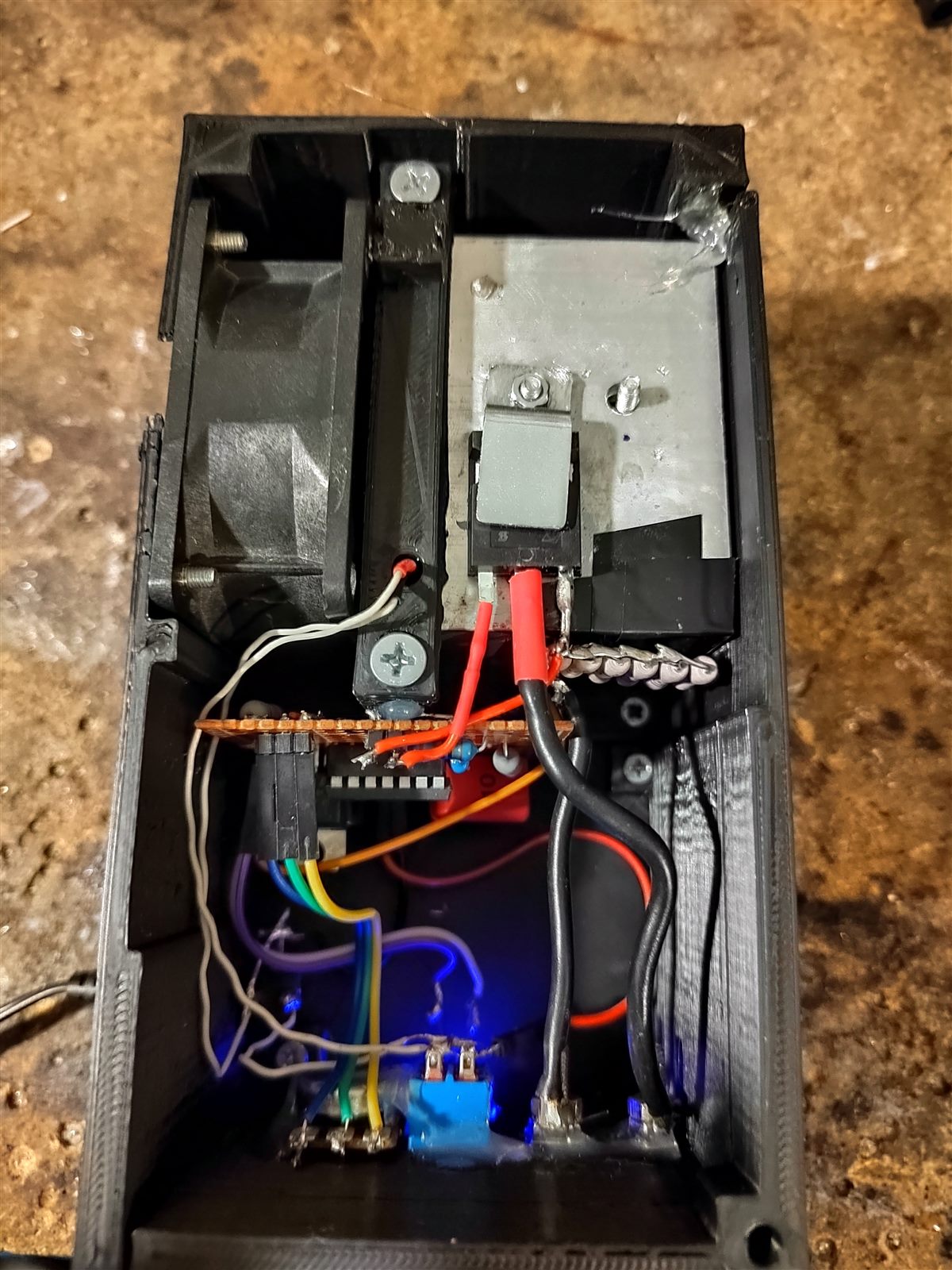
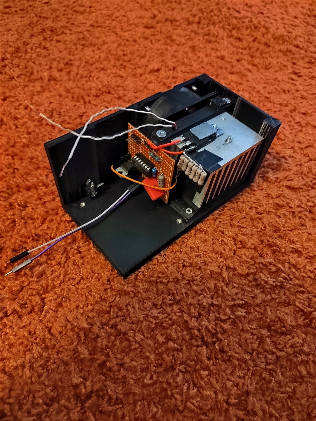
The circuit went onto perfboard. The transistor sits on a heatsink, and the fan on that heatsink runs from the 12 V rail.
A printed box
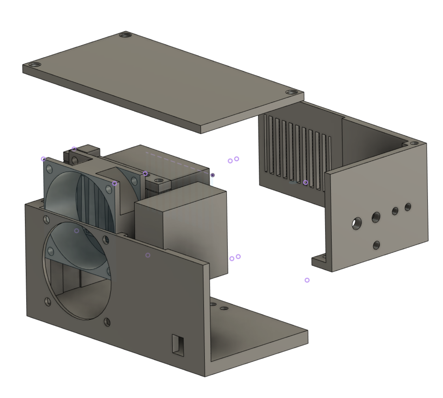
The enclosure is a 3D print, drawn in Autodesk Fusion 360 like the rest of my printed parts. The knob, the banana jacks and the heatsink all land in one shell.
The enclosure
The model is the same box split apart: fan duct, heatsink pocket, and the holes for the knob and the terminals.
It holds while the voltage moves
On the bench the knob runs the load from zero up to whatever the supply will give. In the test that ceiling was 3 A. Changing the voltage across the load leaves the current where it was set.
Stay inside the safe area
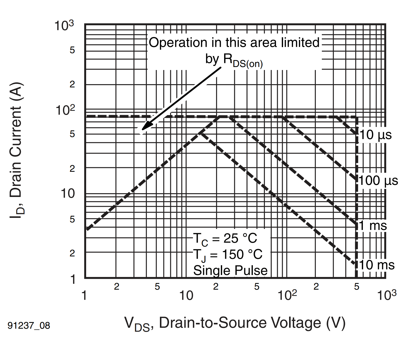
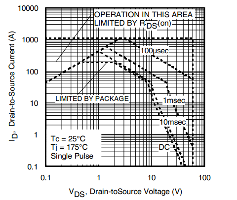
Powered from at least 12 V, the circuit is hard to get wrong, and almost any MOSFET will do. The limit is the safe operating area, not the schematic. The IRFP460 datasheet only draws the 10 ms boundary, not DC. It was not meant to live in the linear region. The die is large enough that it tolerates the loss anyway. The IRFP3006 chart is there as a comparison: a part whose datasheet does show DC, and the DC line is not far from the 10 ms line.
If the op-amp is fed from a lower rail, use a logic-level MOSFET such as an IRLZ44N. The op-amp cannot swing past its supply, and plenty of them are not rail-to-rail, so 5 V on the rail does not mean 5 V on the gate.
What I would add later
For the thesis this is enough. A microcontroller and a measurement of the voltage across the load would turn the same hardware into a constant-power load, and the setpoint could be finer than a potentiometer. That can wait.