
Project / Finished product
DRSSTC I
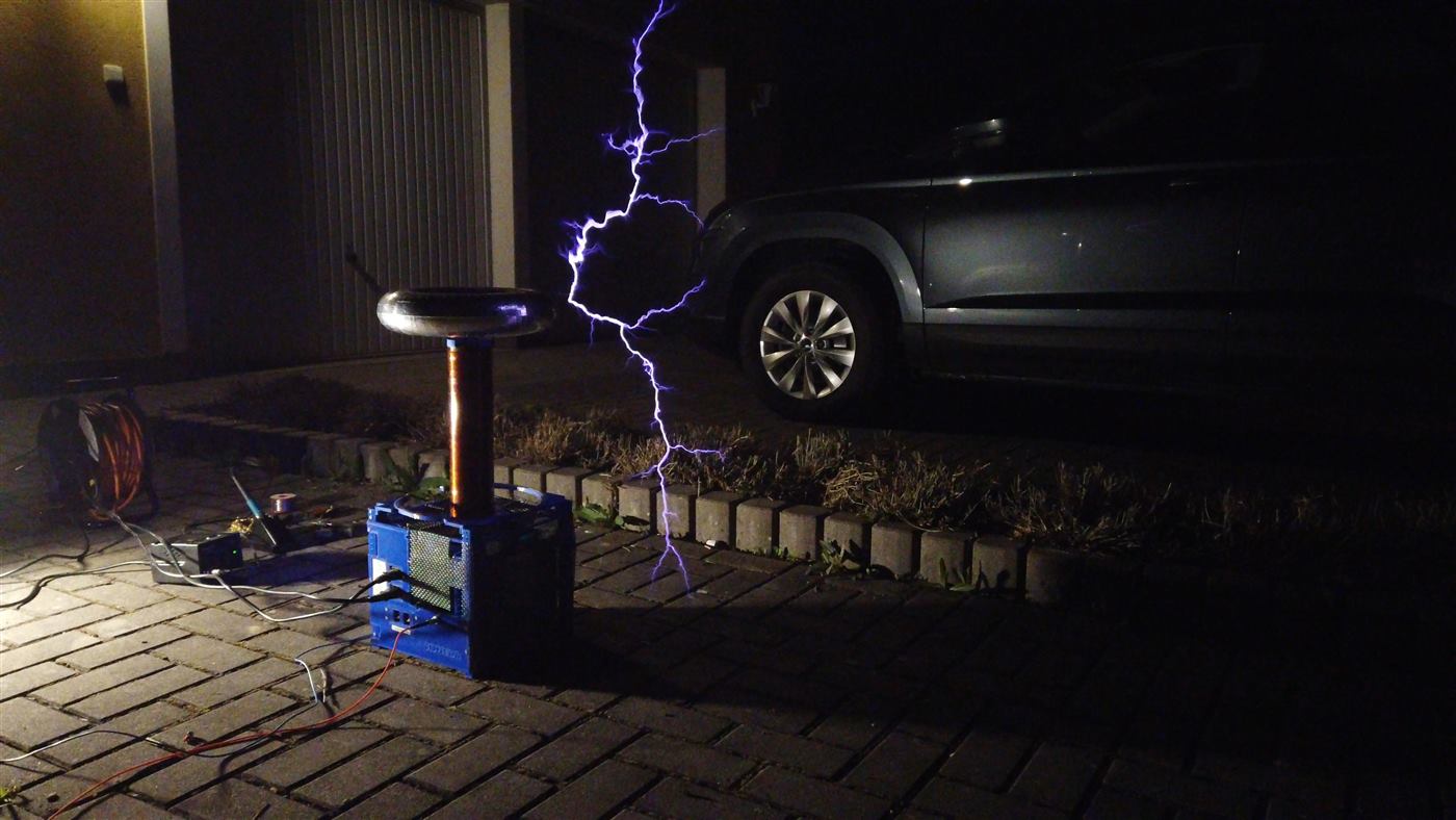
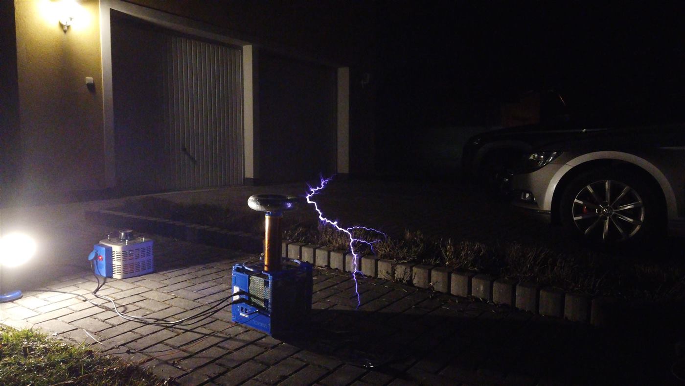
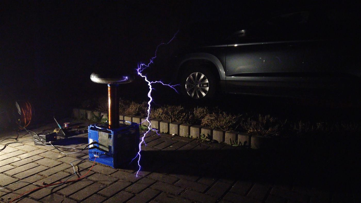
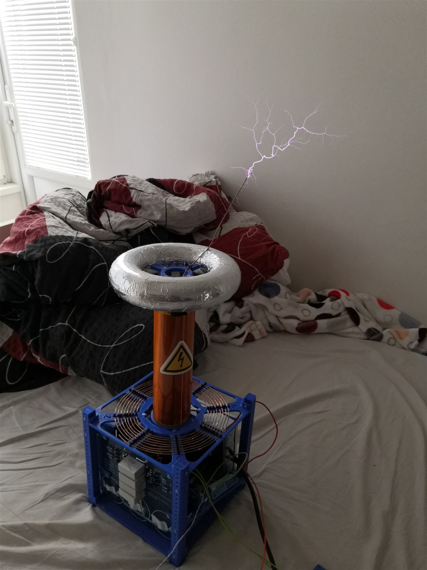
A first Tesla coil, and a first DRSSTC. Started in August 2019, four dead bridges later, then a new secondary and an NTC so it can sit on the mains without a variac.
- Power electronics
- High voltage
- Status
- Finished product
- Bridge
- FGY75T120SQDN
- MMC
- 41 nF · 6 kV
- Primary
- 218 kHz
- Streamers
- 70 cm
At a glance
A first coil
I started this in August 2019. It was my first DRSSTC and my first Tesla coil. Most of what I know about high-power switching and about what a resonant secondary will actually do, I learned by building it.
A first coil is a good way to break parts. I destroyed the bridge four times before it would run, and the IGBTs were the part that kept paying for the lesson.
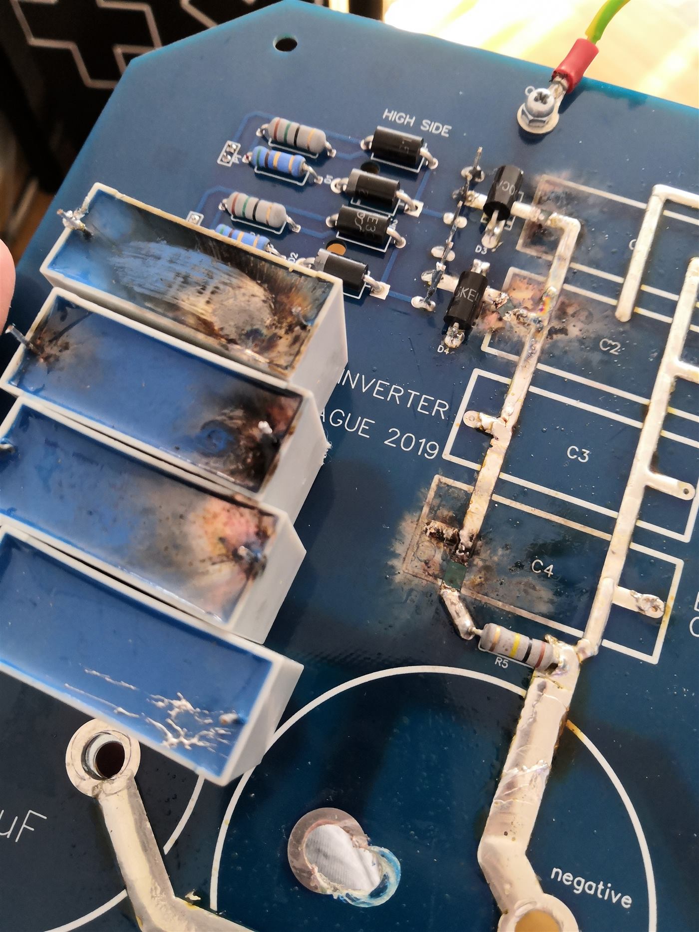
Four bridges
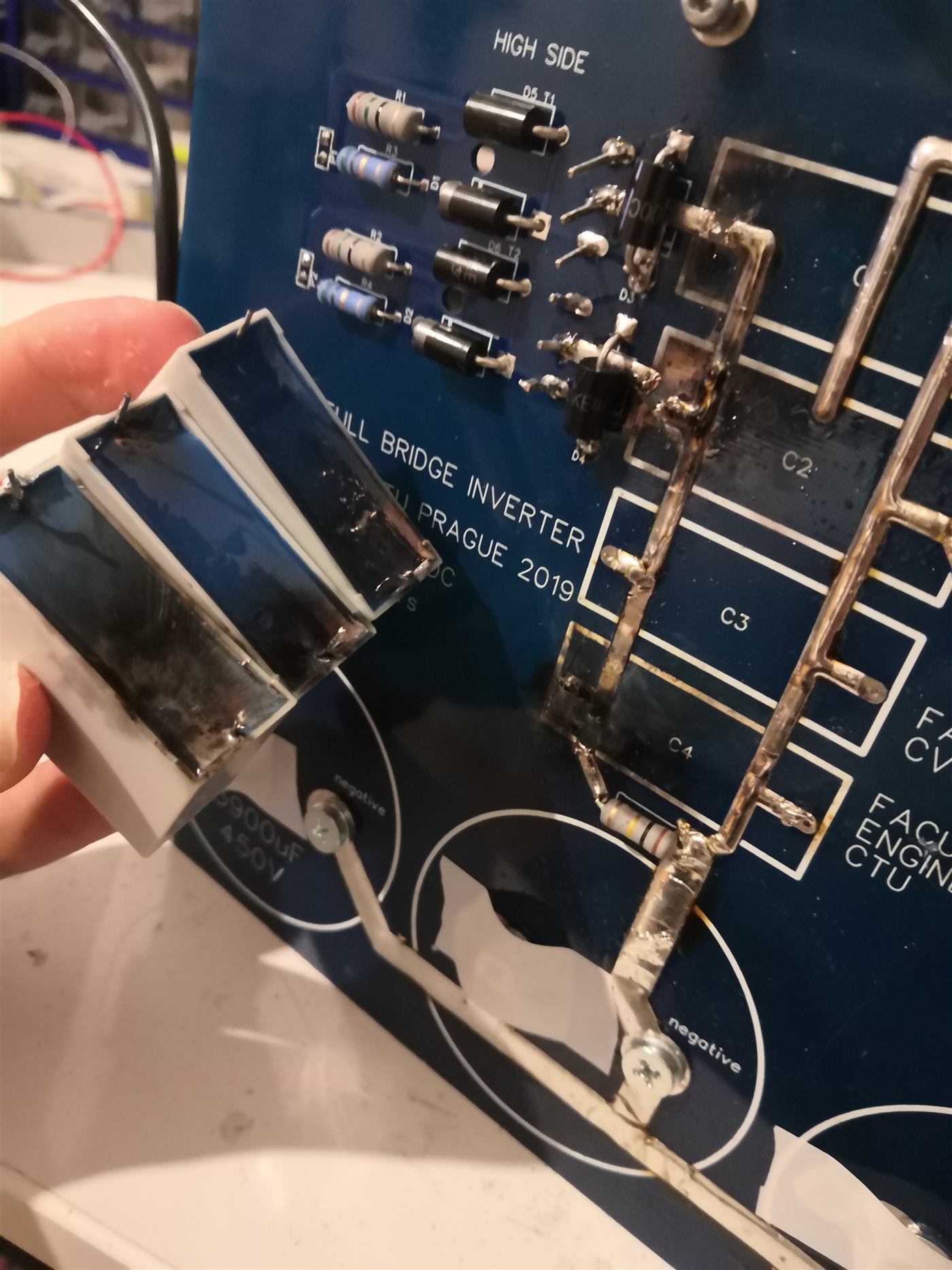
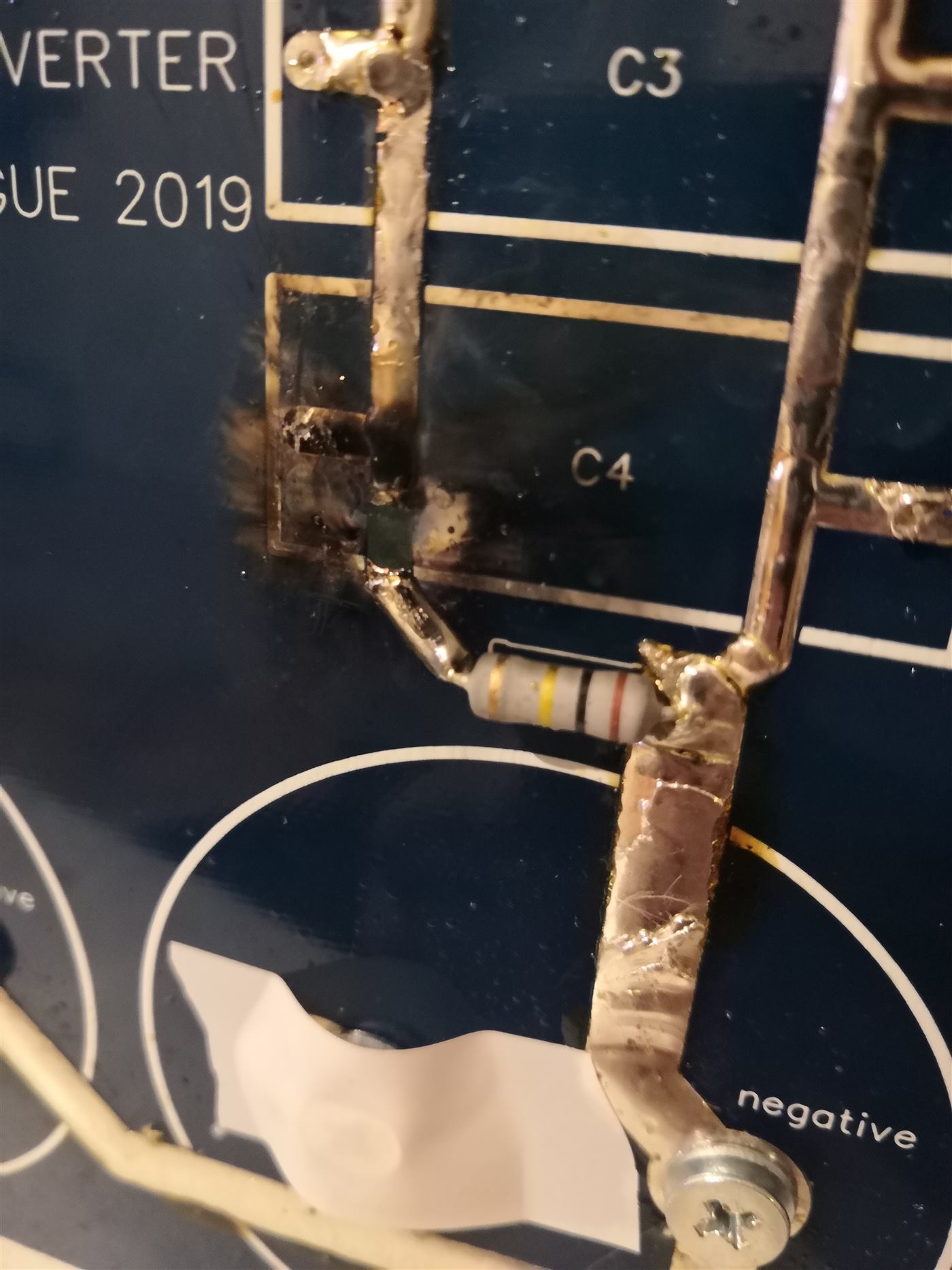
The first one went in September 2019. I turned the power up with no ground-strike rail. A streamer from the secondary found the primary, and the IGBTs went with it.
Two months later I was still guessing what “too much” meant for the transistors. Ontime was 200 µs and there was no overcurrent trip. Those TO-247 parts were switching something like 600 A at 218 kHz. They did not last. The bang was loud enough to make the point: 200 µs is too long, and the coil needs an OCD.
The third bridge died at the end of February 2020, after the coil had finally started to behave. OCD was in, ontime was about 40 µs, and I was close to full mains. I wanted the voltage on the bridge and I probed it with a homemade twisted pair. The insulation was nowhere near 300 V. It broke down, shorted the bridge, and took another set of IGBTs. The fourth was the first test on full mains, in the summer of 2020. I had 440 V TVS diodes across the bridge. The spikes were long enough to cook one of them into a short, and the bridge followed. After that I fitted 1200 V IGBTs and 880 V TVS diodes. With that headroom it holds, even above 250 V on the input.
The driver came first
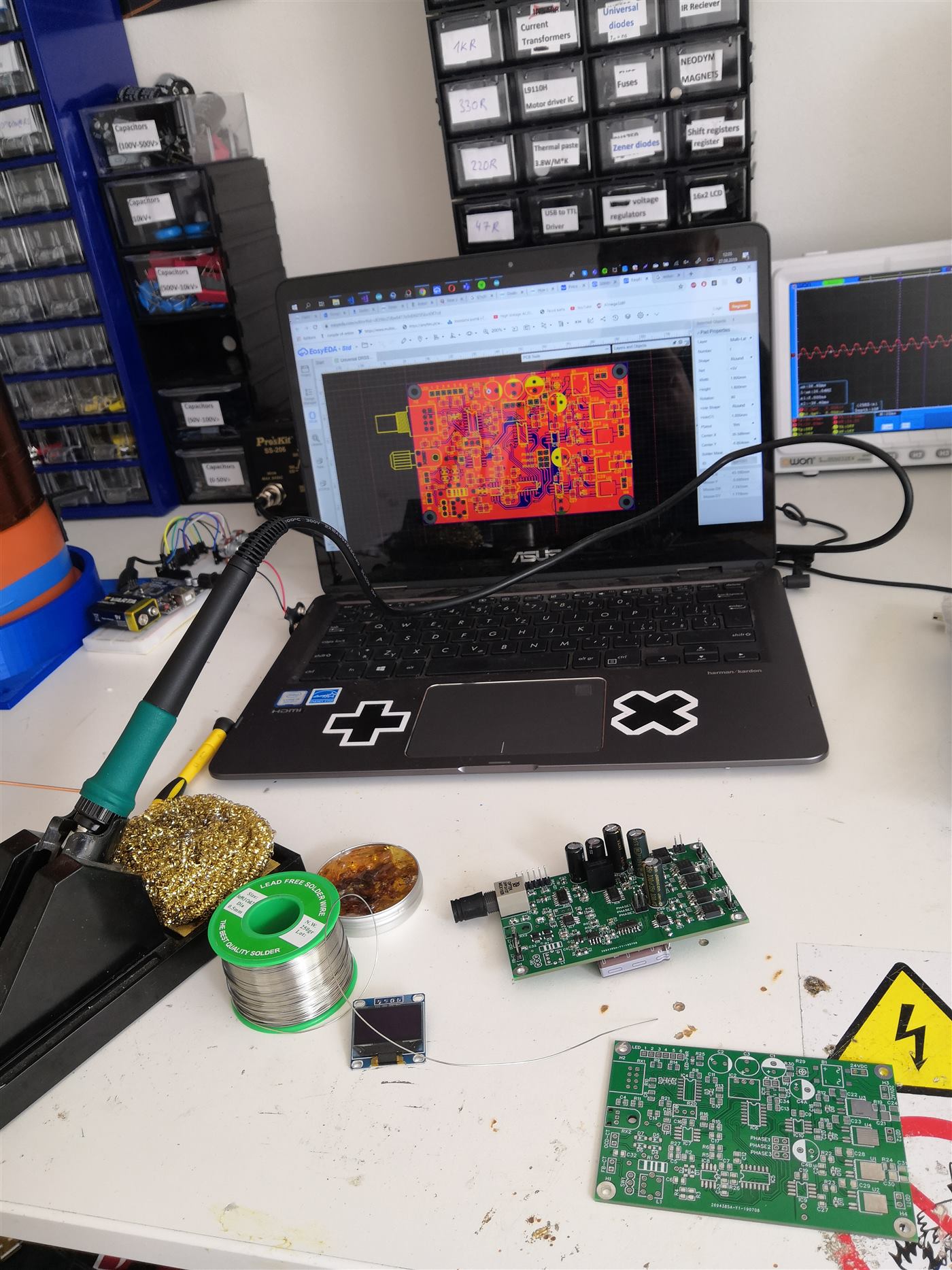
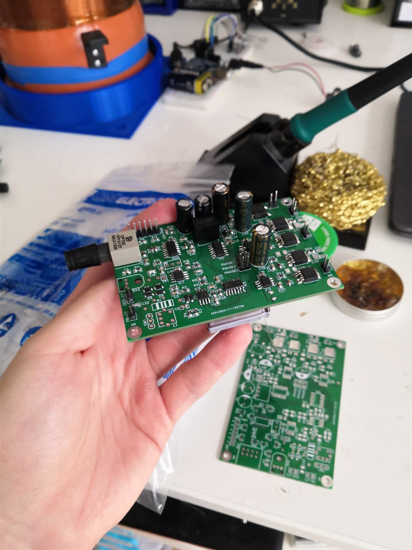
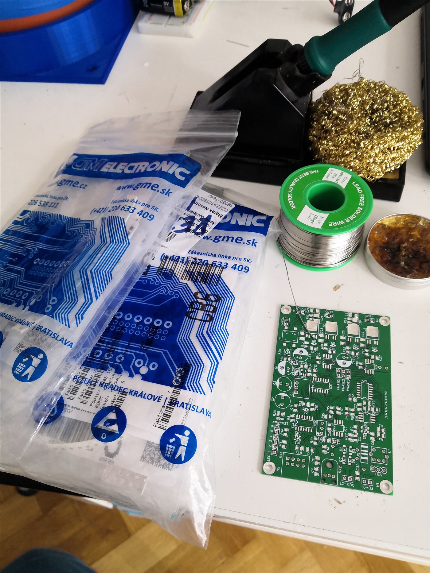
The UD2.7 was the first thing finished. I bought the board and the parts and soldered it up. Two boards, because the parts are cheaper in quantity and I already knew this would not be the last DRSSTC.
The PCB had two small errors. The optical receiver footprint was wrong and shorted the board, and one resistor divider had no ground. Once those were fixed, the driver ran the first time I powered it.
Secondary, MMC, bus
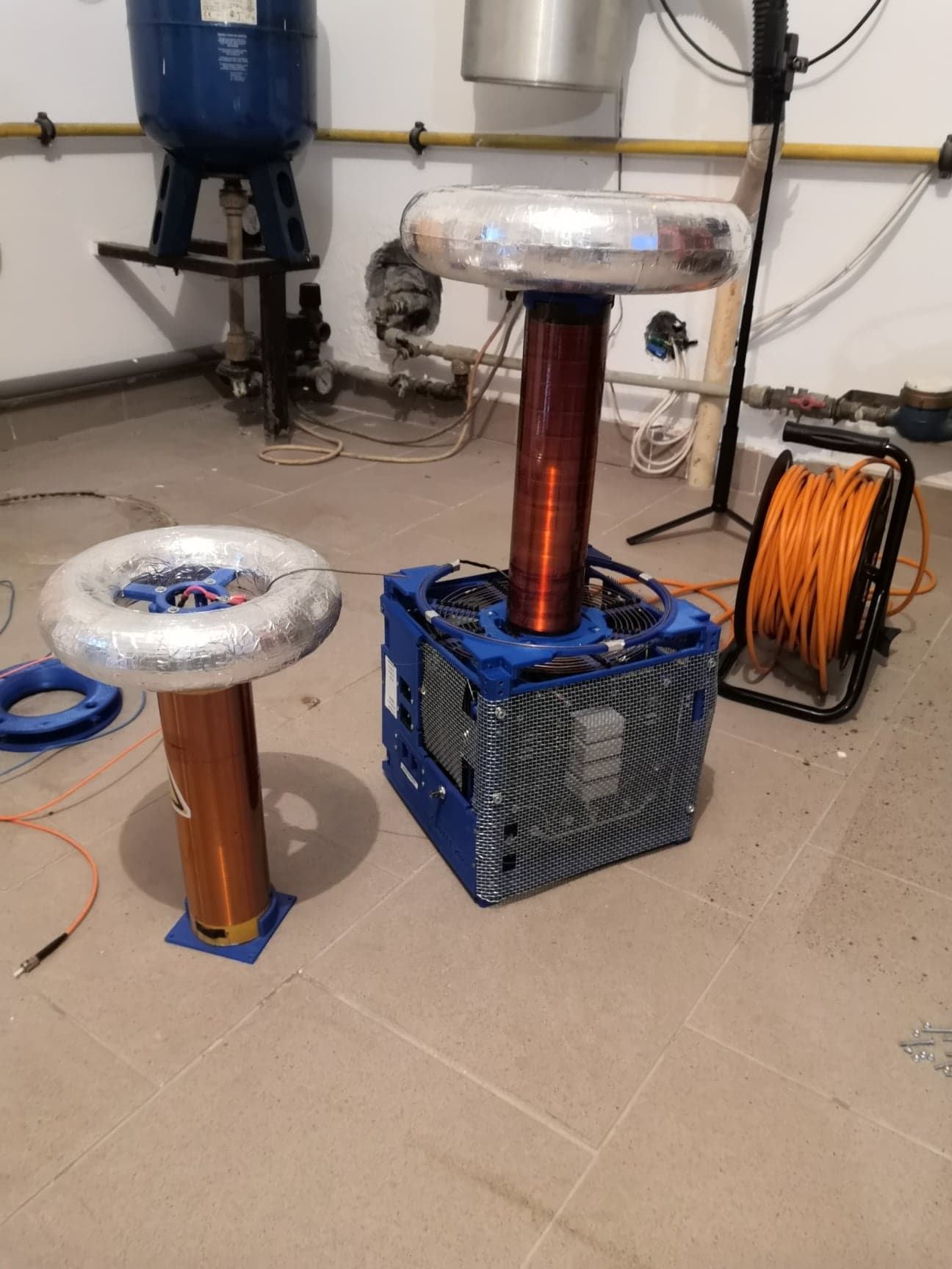
The first secondary came from eBay: about 1680 turns of 0.15 mm wire. The topload is a 3D print wrapped in aluminium tape. With the topload on, the secondary sits near 240 kHz. The MMC is Tesla TC343 capacitors, 6 kV and 42 nF, tuned with the primary to 218 kHz. The same capacitors are the snubbers, on a board I drew for the bridge. The driver supply is a Mean Well 24 V, 3 A supply, shut in a metal box with the driver so the coil cannot talk to it. The DC bus is three 400 V, 3800 µF capacitors in parallel.
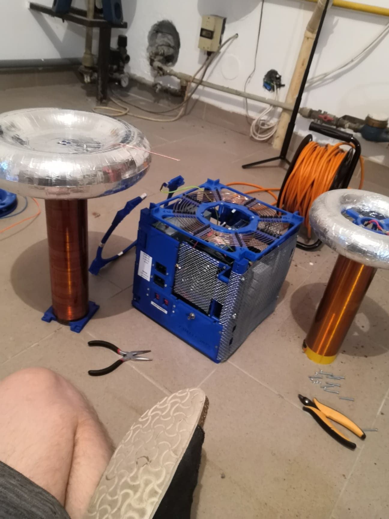
After the case was printed and the rest was bolted in, it looked like a coil. Scoping it was another matter. That close to a running secondary, the EMI makes a clean trace hard to come by.
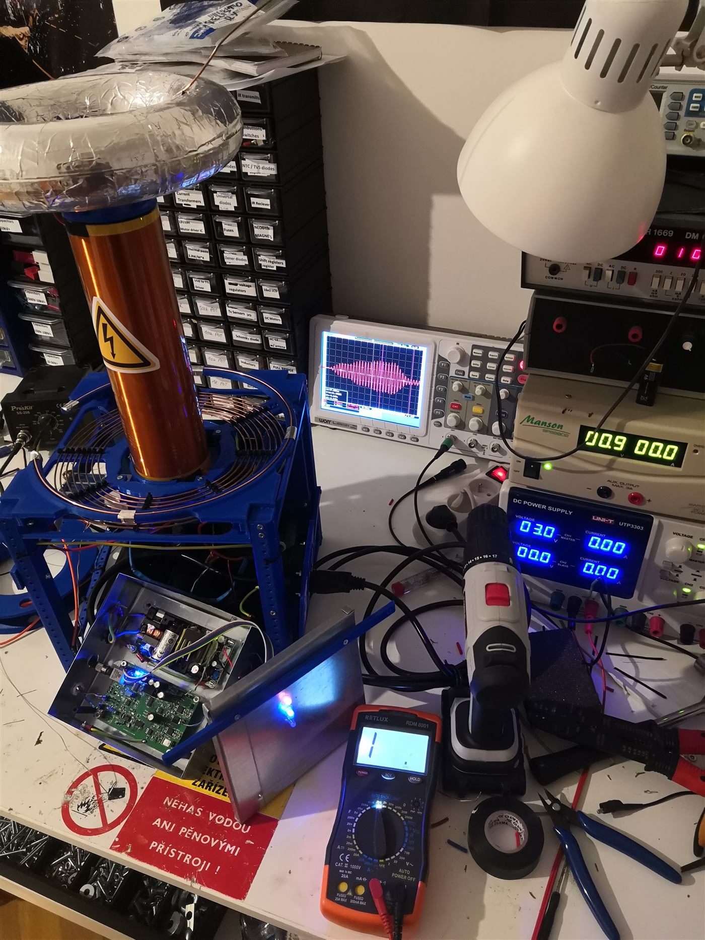
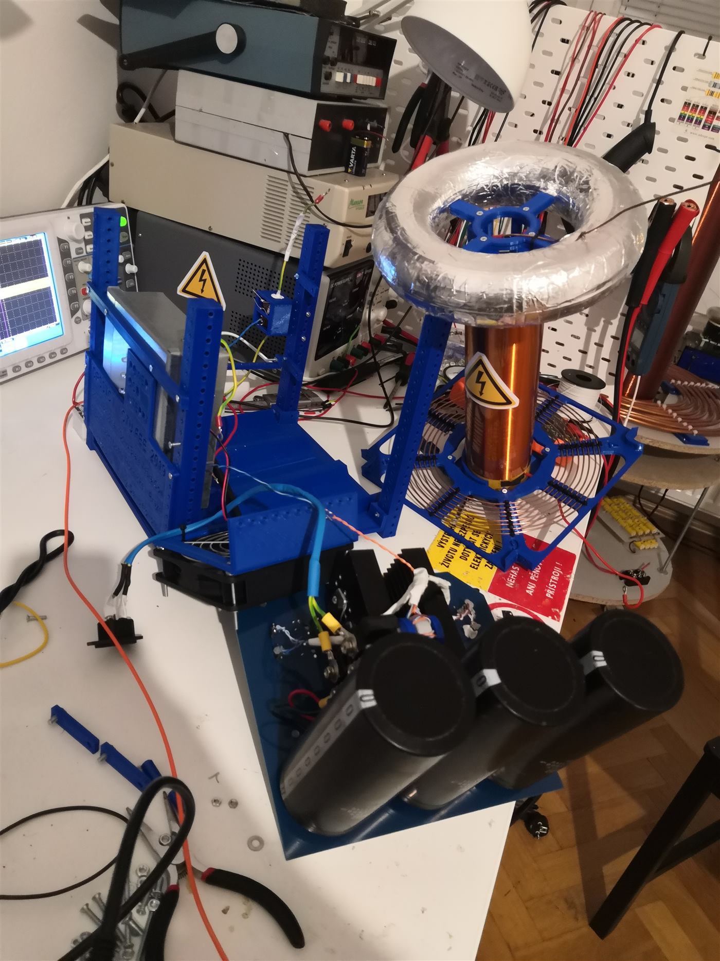
What the scope could still see
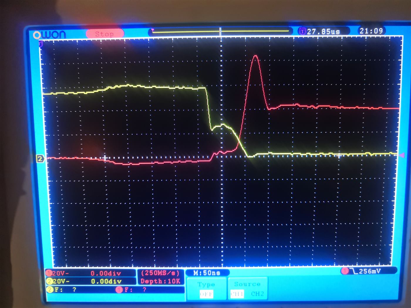
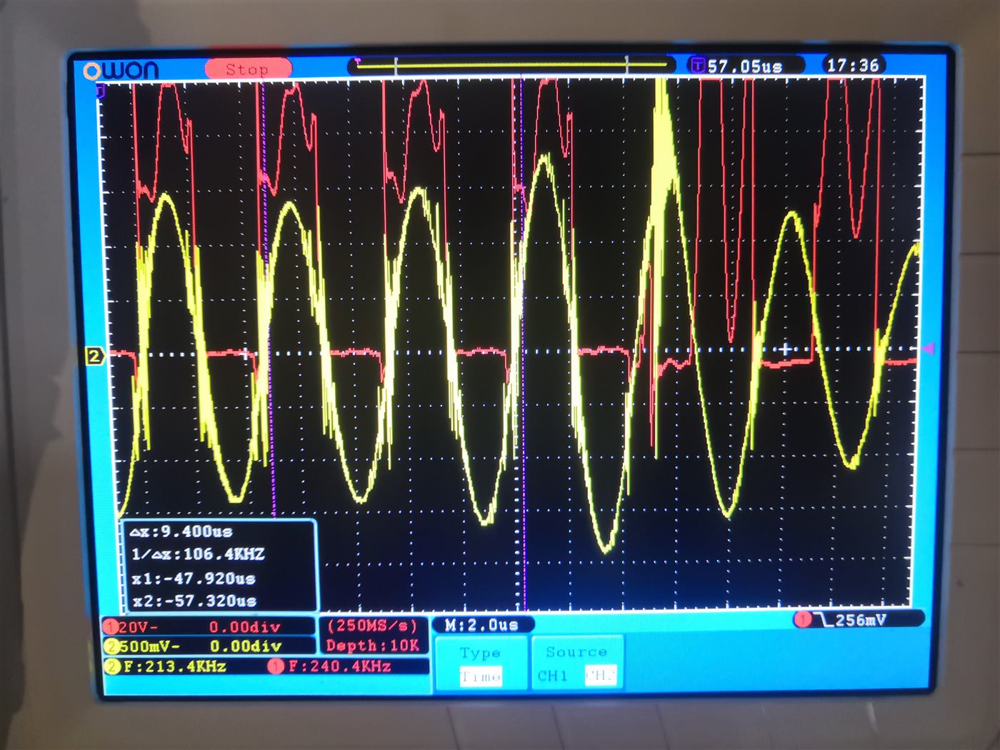
At low power the gates and the primary current are readable. Closer in, the bridge voltage during the switch is still a useful picture. Turn the power up and the interference swallows the trace. The shape is still there. The numbers get optimistic.
That was the state of it for a long time: a coil that ran, and a measurement setup that argued with it.
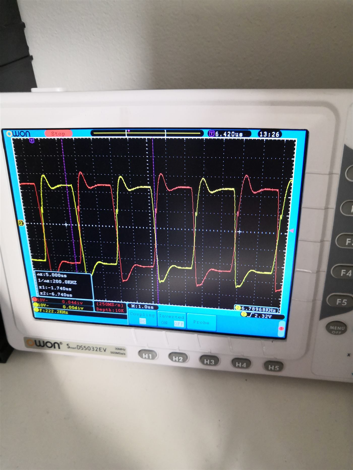
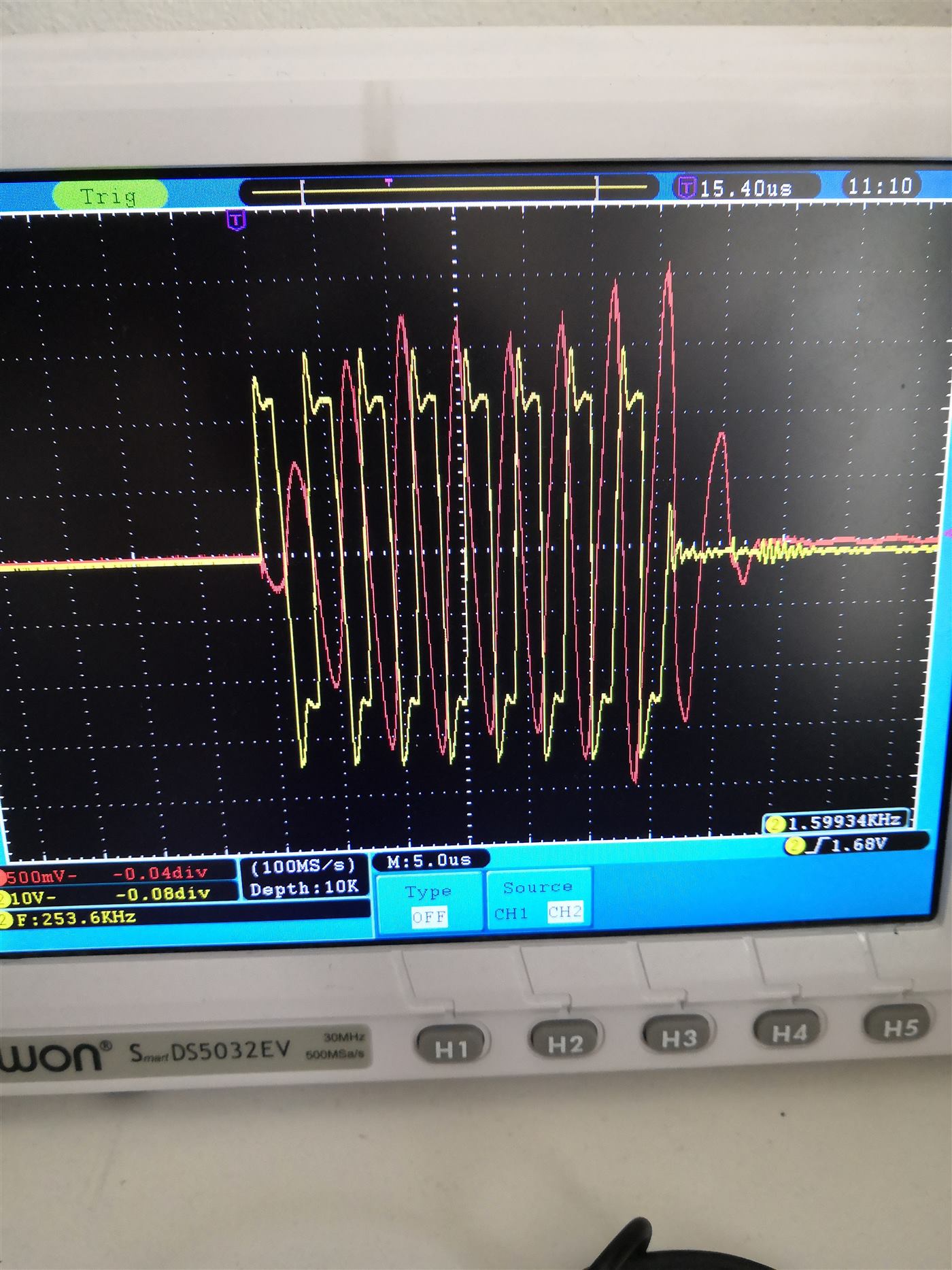
Mains, then a dead secondary
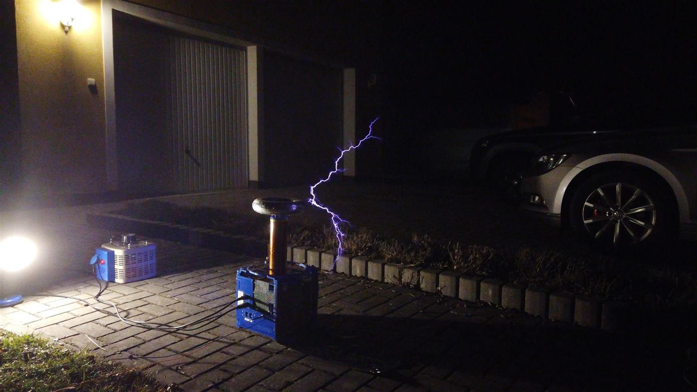
On 1 April 2021 it finally ran from the mains. Not finished. At mains voltage the secondary insulation broke down, so it needed a new winding, and the inrush into more than 11 000 µF was too much for a breaker and for the bridge rectifier. Until then the input was a variable transformer.
Even so, the streamers were already in the 60 cm range, about 2.5 times the height of that secondary. I was happy with it.
Wound again
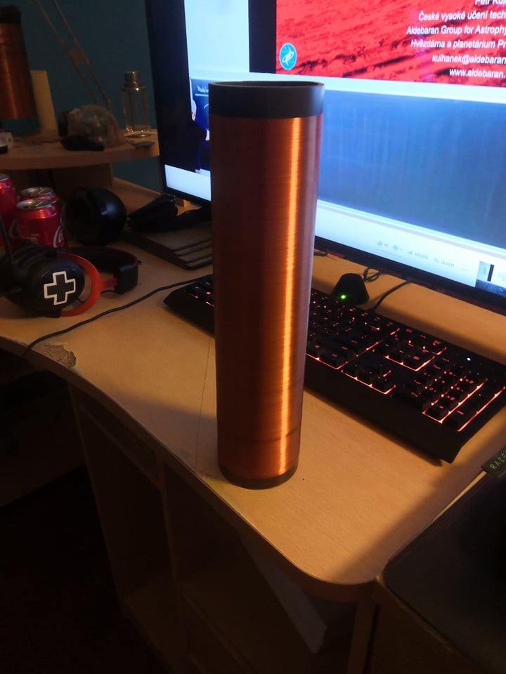
The old secondary was 24 cm by 6.5 cm, 1680 turns of 0.14 mm, bought long before I wound anything myself. The new wire is 0.2 mm, about 1300 turns, on a slightly taller former. Thicker wire and fewer turns was the point: the secondary resistance drops, Q goes up, and a tuned coil makes more voltage.
The old winding was about 400 Ω. The new one is about 160 Ω, and the enamel is two layers, which is what the first secondary did not have when it broke down.
The ratio of streamer length to secondary height stayed about the same. The secondary is taller, so the streamers grew anyway, with 400 fewer turns.
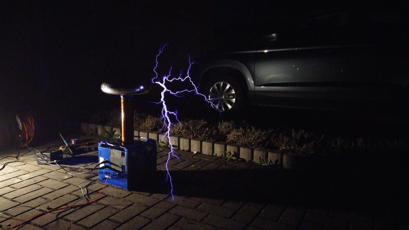
Ground strikes
With the new secondary in place the strikes got longer. The longest I measured was 70 cm, still about 2.5 times the winding height.
NTCs instead of the variac
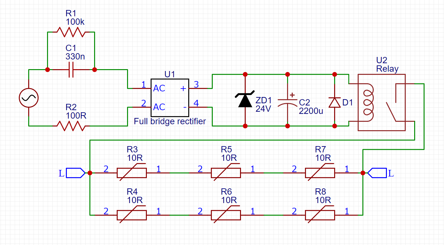
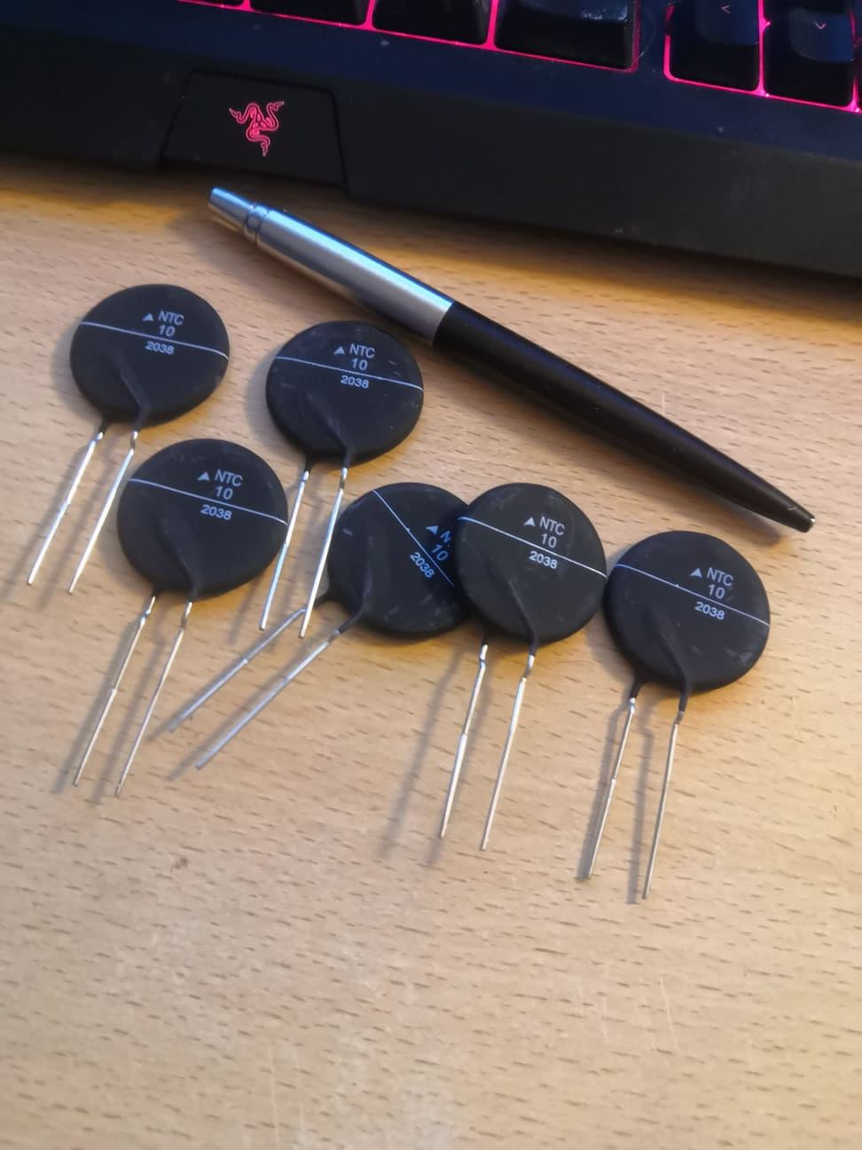
Once it would live on full mains, hauling a 30 kg variable transformer around only to tame the inrush stopped making sense. The replacement is crude: six large NTC thermistors, and a capacitor-dropper supply that pulls in a relay to bypass them.
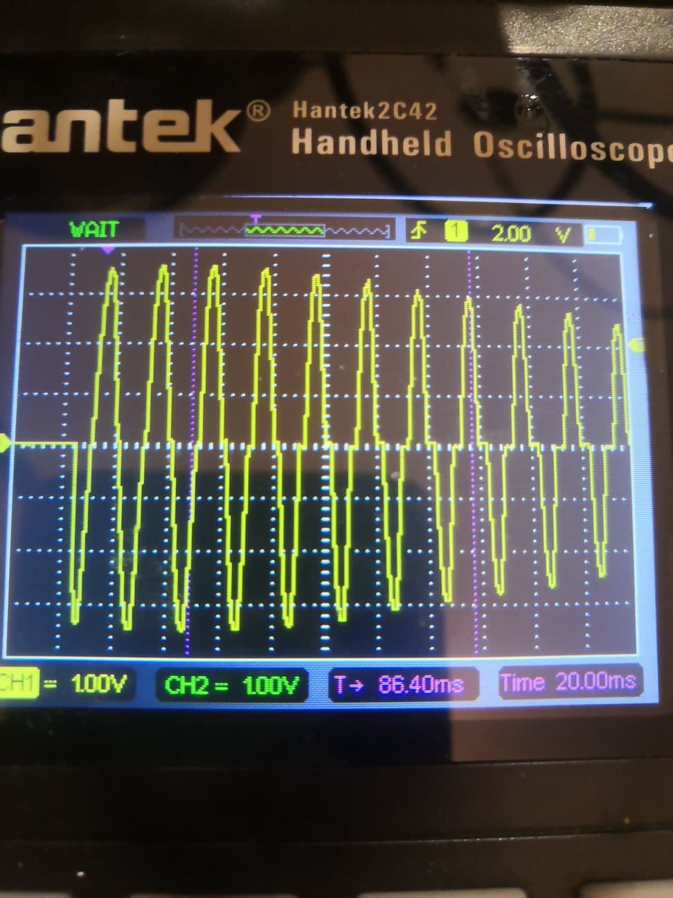
The scope shot is 10 A per division with the NTCs in circuit. I also measured the inrush into a 20 000 µF bank the same way. It is not elegant. It is small enough to leave on the coil, and the breaker survives.
As it stands
Primary a little under the secondary, OCD at about 400 A, ontime capped at 60 µs. That is the coil that survived.
Specification
- Bridge: FGY75T120SQDN
- MMC: 4S2P Tesla TC343, 41 nF, 6 kV
- DC bus: 3 × 400 V 3800 µF, 11 400 µF
- Primary: 8 turns of 1.5 mm, tapped at 6.5, 218 kHz
- Secondary: 1270 turns of 0.2 mm, 28 × 6.75 cm, 168 Ω, Q about 190, about 236 kHz with the topload
- Topload: 30 × 7 cm, aluminium tape on a printed form
- Ontime: 60 µs, duty limited to 8%
- OCD: about 400 A
- Input: mains, up to 250 V AC
- Streamers: 70 cm, 2.5× the secondary height