
Project / Finished product
DRSSTC III
A long-pulse coil. Pulse-skipping, on-times up to 3 ms, and a copper topload after the first one started hitting the primary.
- Power electronics
- High voltage
- Status
- Finished product
- Bridge
- CM150DY-12H
- MMC
- 50 nF · 9 kV
- On-time
- 3 ms
- Streamers
- 130 cm
At a glance
Long pulses
Pulse-skipping has become the usual way to run a DRSSTC hard. When the current hits the OCD threshold, the driver does not wait for the next enable pulse. It only holds the bridge off until the primary current falls back under the limit, then it starts again. On-time can go up, and so can the power. The arcs get thick even at a low break rate. The other use is the opposite: keep the primary current down and make up the energy with a longer on-time, so a powerful coil can still sit inside the IGBT ratings.
Chris Ralph, Frederick Hamilton and Florian Delmas were already doing this. Hamilton’s coil is written up at highvoltageforum.net/index.php?topic=1430.0. The driver notes I keep coming back to are at classictesla.com/pslawinski/udplus.html.
The one that is allowed to run hot
Calling this my first long-pulse coil is only half true. DRSSTC II already has a pulse-skipping driver. On that coil the skipping is there to hold the primary current down, inside the datasheet, because it goes out on shows and it has to survive them.
This one is the other use. Primary current above the rating, and on-time in the milliseconds. The point is to see where the coil actually stops.
CM150s, and another UD+
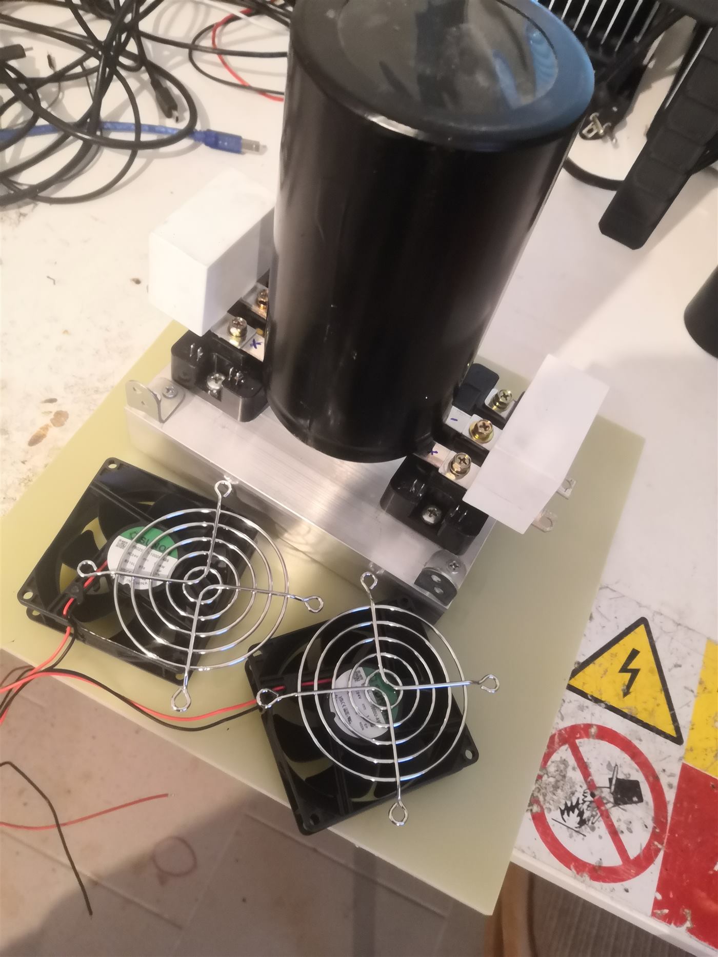
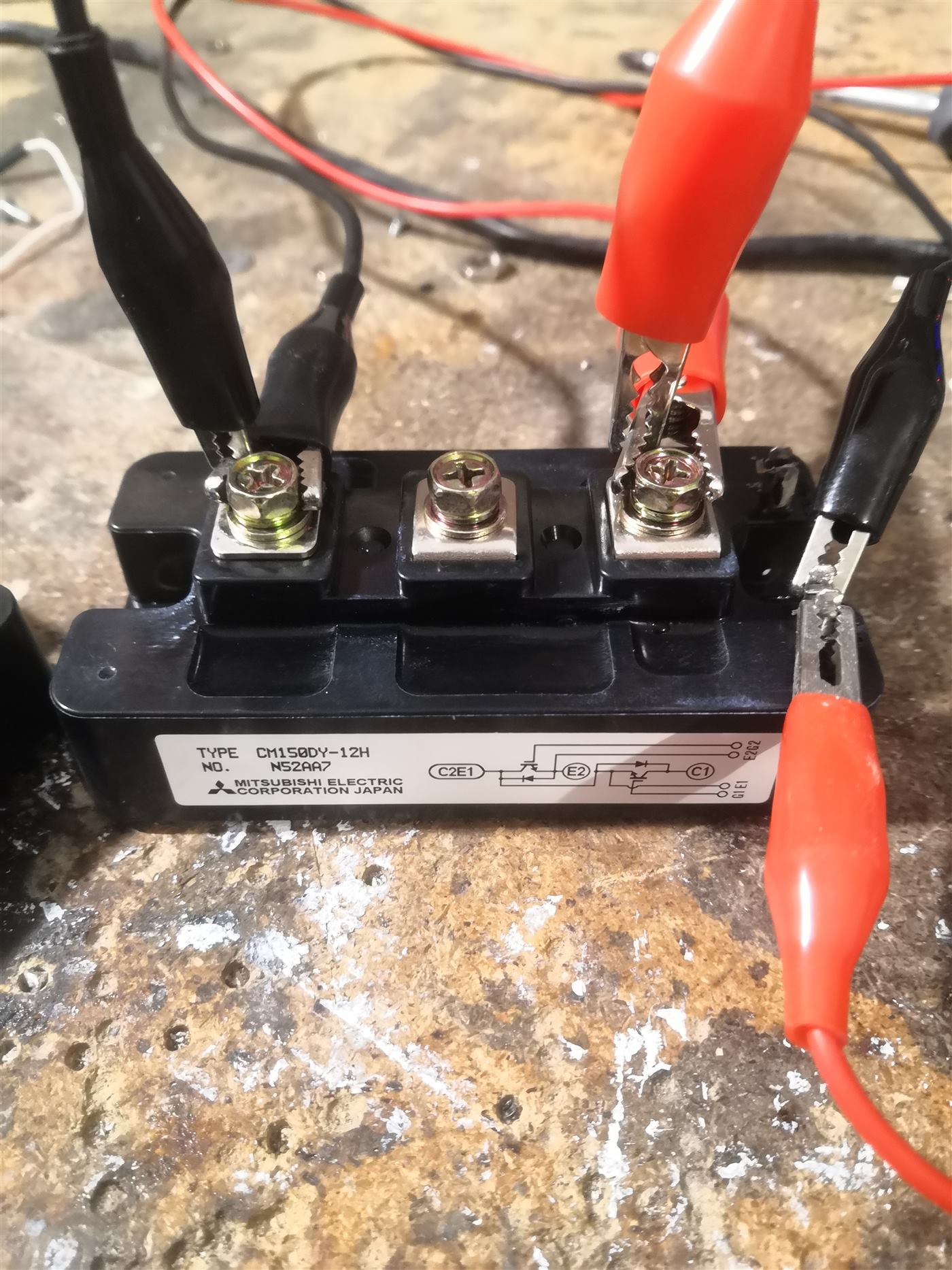
I already had some CM150DY-12H modules, about 8 dollars each. The datasheet is at pdf.datasheetcatalog.com/datasheet/powerex/CM150DY-12H.pdf. They went onto a heatsink from TME, tme.eu/, with a 10 000 µF, 450 V bus capacitor and 1 µF, 1.2 kV snubbers. The snubber datasheet is at farnell.com/datasheets/3360985.pdf.
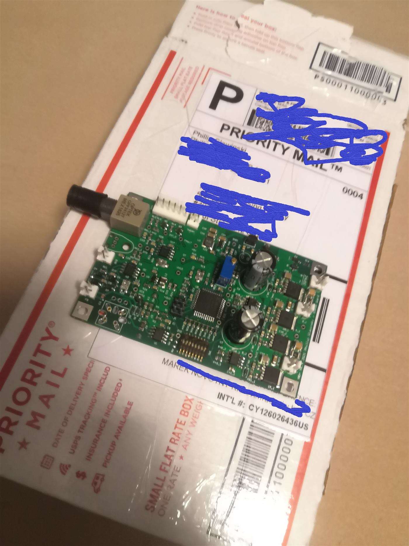
The driver is another UD+ from Philip Slawinski. Its supply is a small iron-core transformer, about 50 W, around 18 V AC. Rectified, that is over 25 V, which is more than the driver wants, so an LM317 holds the rail at about 22 V.
A red box
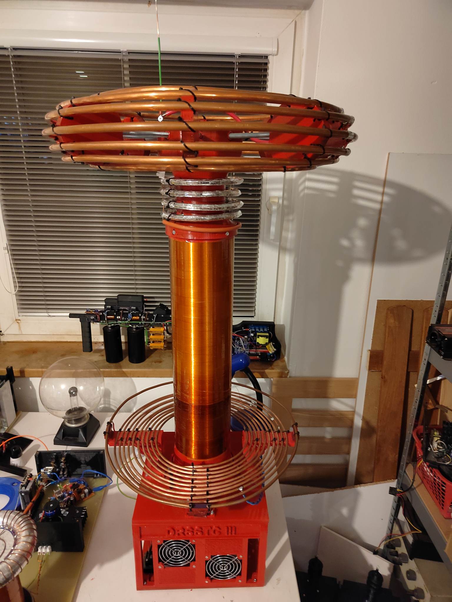
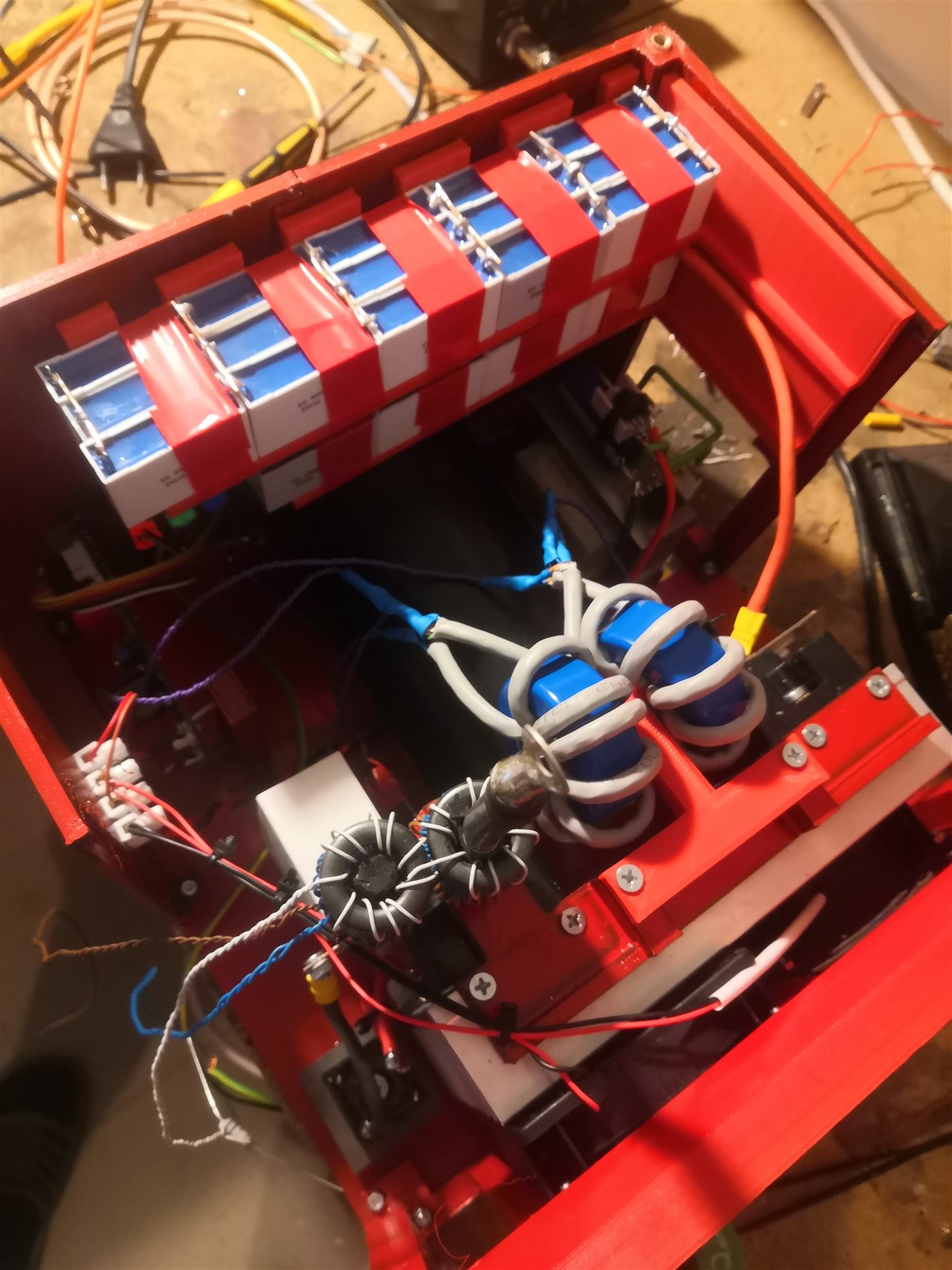
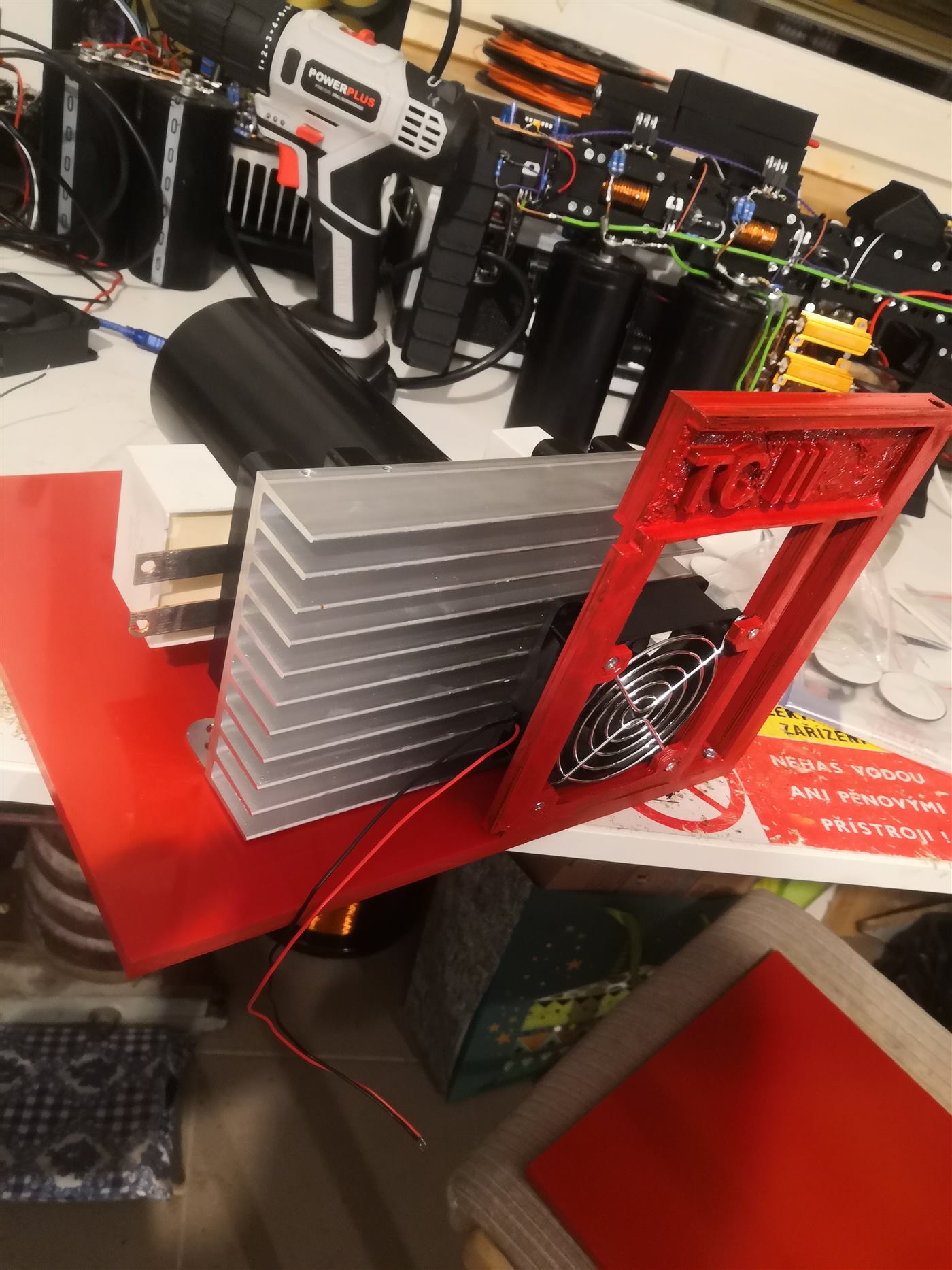
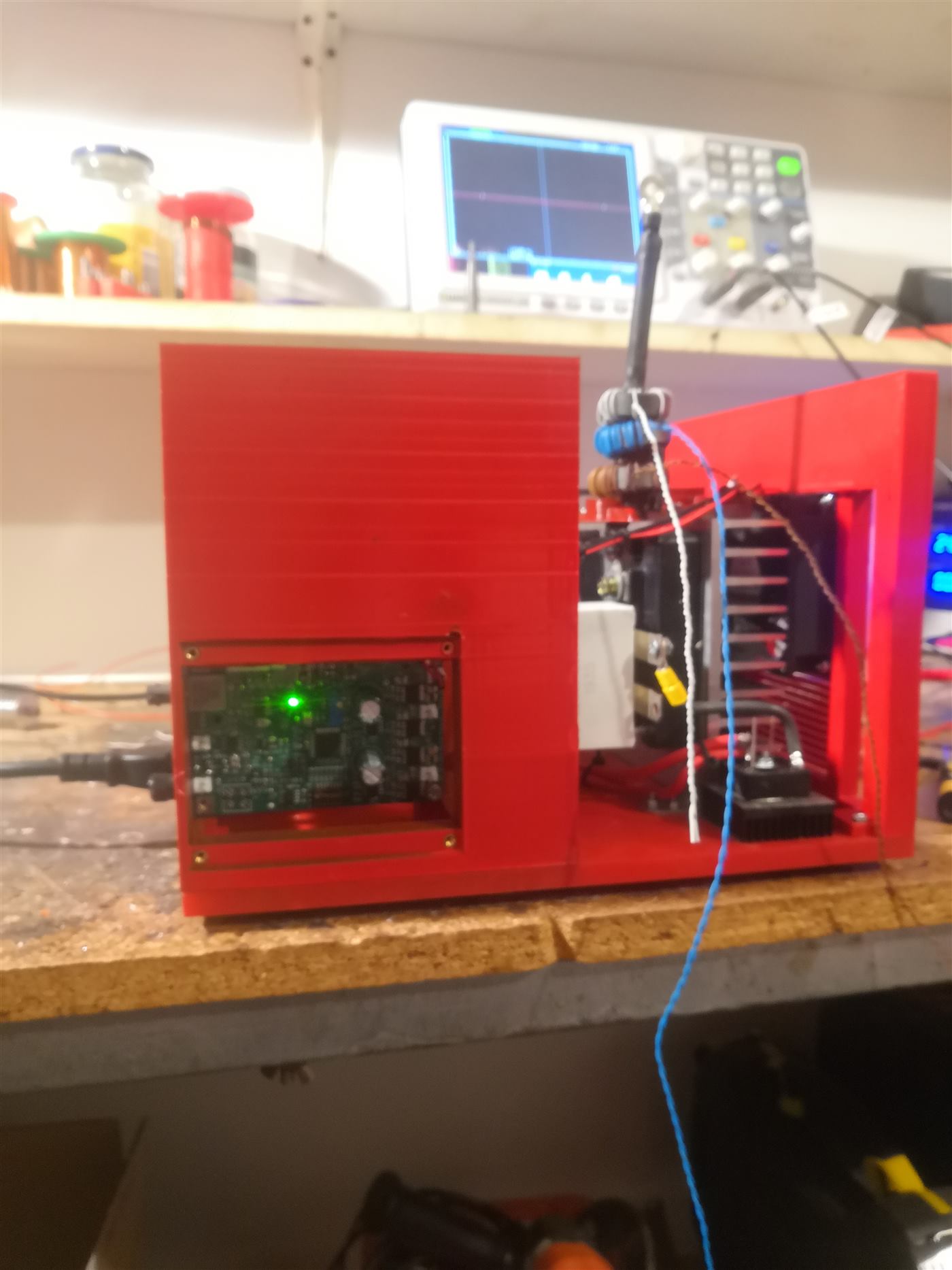
After the printed parts were done I had a rough layout: bridge, fans, heatsink, driver. The case got painted red. The current transformers sit with the driver.
At that point it was a compact box and not yet a coil. The MMC, a soft start and a fuse were still missing.
Fifty nanofarads, and a lot of primary
The MMC is Tesla TC343 pulse capacitors, 150 nF at 1 kV, the Czech ones I already trust. Nine in series, three of those strings in parallel: 50 nF at 9 kV. They have been fine in a DRSSTC every time I have used them.
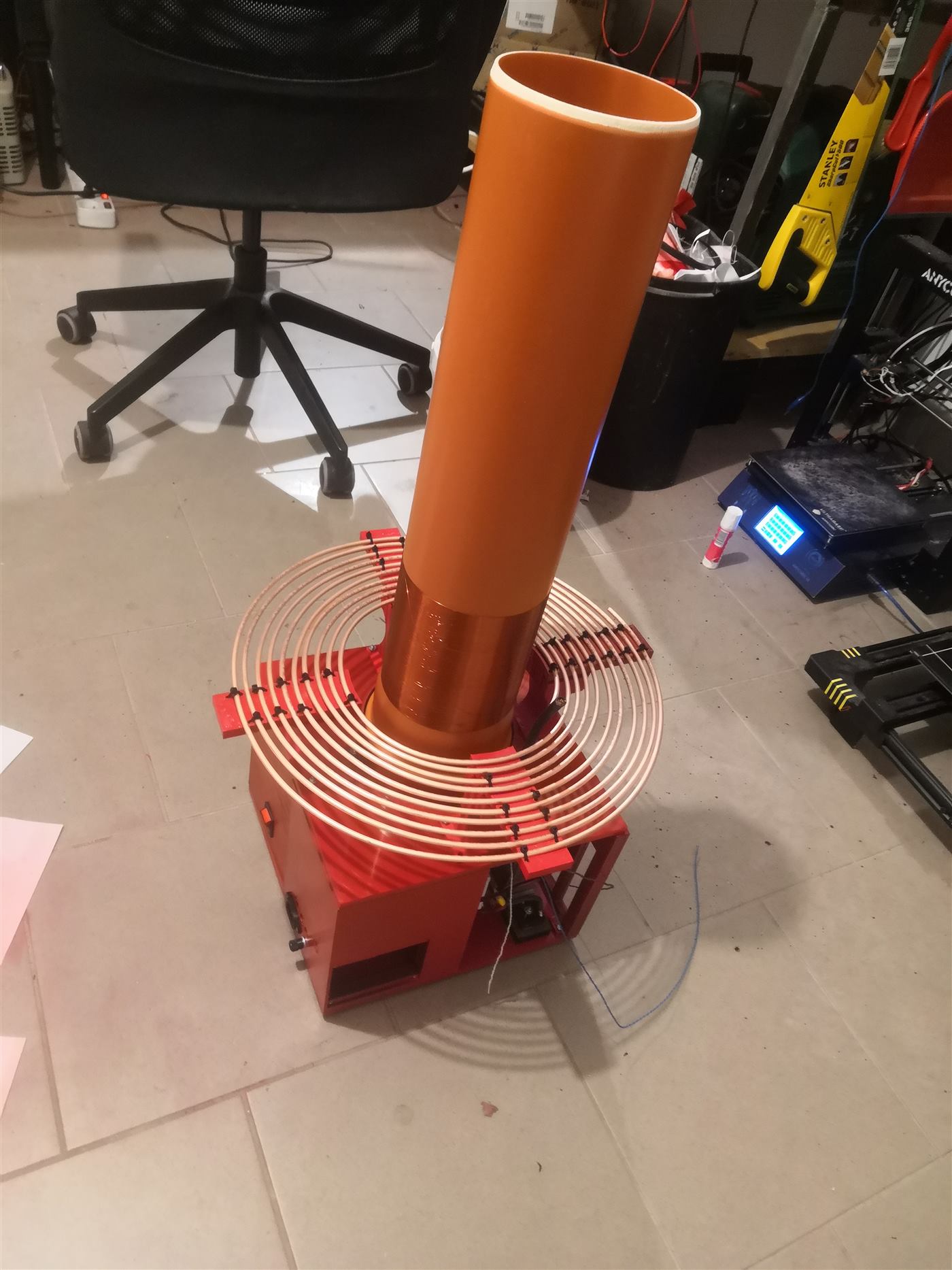
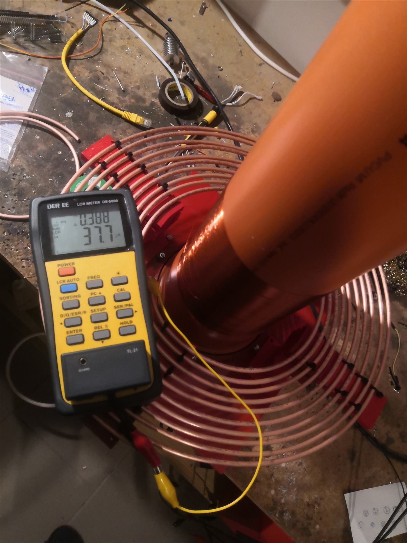
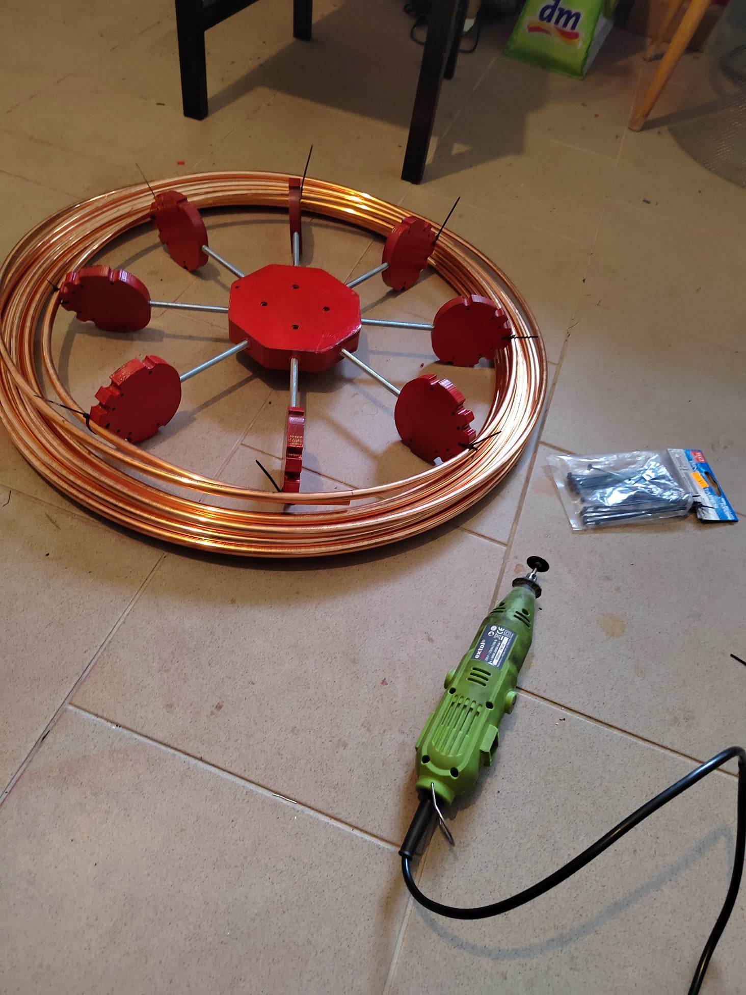
The primary is 8 mm copper tube. I wanted a lot of turns, at least seven, so the primary impedance would be high. It wound cleanly. The mistake was in the secondary.
The wire ran out
Somewhere in the arithmetic I got the wire length wrong, and the spool ended before the winding did. I bought the rest and soldered it on, carefully, then buried the joint in varnish and Kapton. Measured primary inductance was 37.7 µH. With the 50 nF MMC that tunes down to about 117 kHz.
The secondary came out higher than I had planned. In this setup the primary is only tapped at about 5.5 turns, which is not the high-impedance primary I was after. It works, and rebuilding it was not worth it. The winding is 0.3 mm double-coated wire on 12.5 cm PVC, about 45 cm long, about 1300 turns.
An iron pan as a load
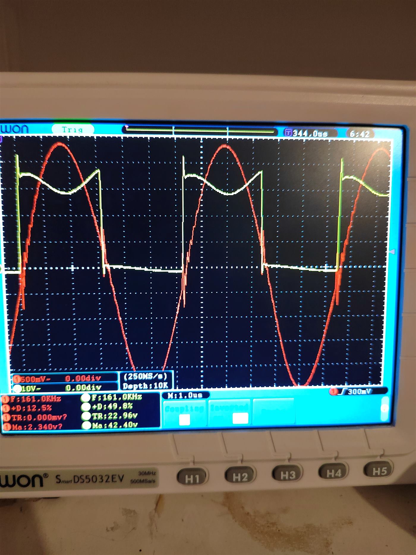
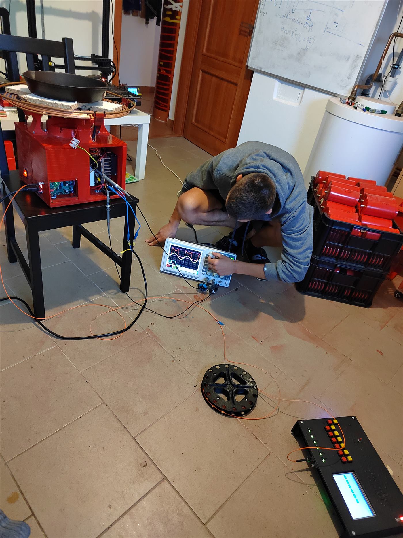
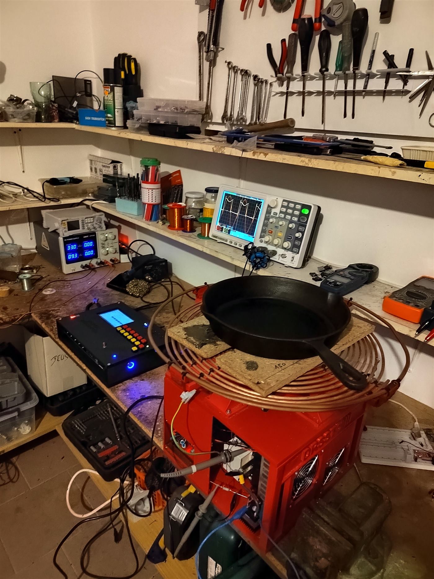
Tomáš helped tune the phase lead on the UD+, and we set the primary current limit at about 450 A. On a static load the coil drew well over 2 kW. We left an iron pan on it for more than five minutes. The IGBTs did not climb even 5 °C above the room. The switching has to be doing almost no work. The scope shows collector-emitter voltage on a low-side device, yellow at 100 V per division, and primary current in red at 100 A per division. It is close to zero-current switching.
The pan was the limit, not the bridge. A few more minutes and the wood under it would have caught. The primary was heating hard as well. After that I was willing to put the secondary on and turn it up.
Three milliseconds
The first high-power run, secondary in place, was over 3 kW with on-times up to 3 ms. The soldered joint in the secondary, the part I was most worried about, held. The tuning did not. A long-pulse coil can throw sparks out to about five times the secondary. I was lucky to get three.
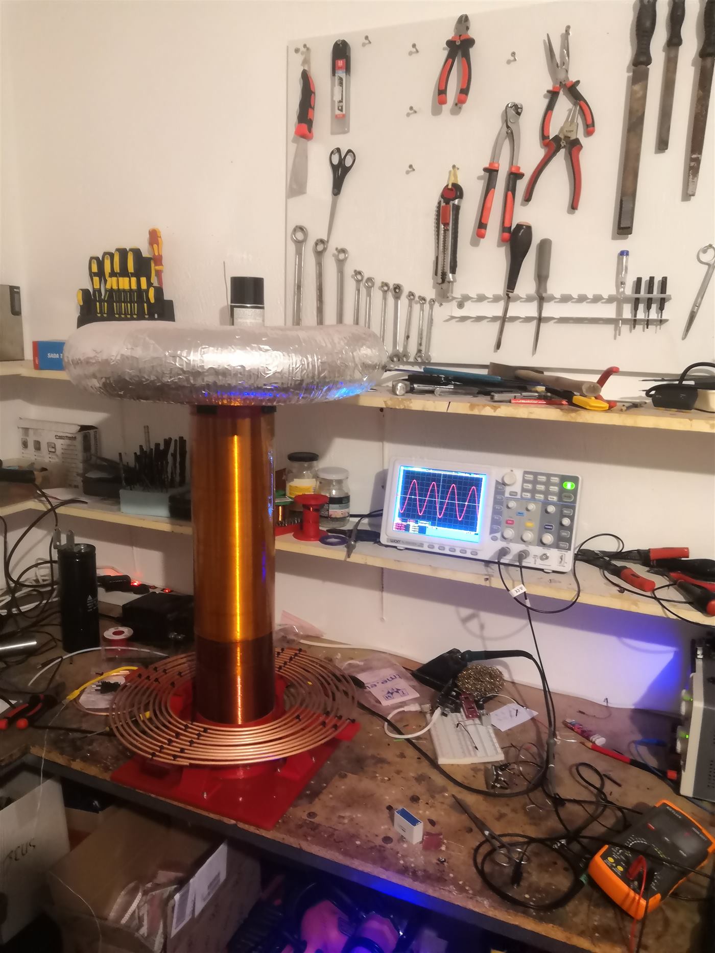
The topload was aluminium tube wrapped in several layers of aluminium tape. Cheap, and not smooth. Arcs left from several places at once. At a low break rate they wanted the strike rail, and a few found the primary. That is how bridges die. These IGBTs survived it. The topload had to get smoother, and larger.
Copper, for Christmas
By 25 December 2022 the topload was 10 mm copper tube on printed spacers. Smoother, and a bit larger: a kinder field, so fewer racing sparks and fewer hits on the primary, and enough capacitance to make up for a skeleton that is mostly air. I also lifted it, and between the secondary and the toroid there are four printed rings covered in aluminium tape, instead of a single wire. Racing sparks and primary strikes stopped. The tube cost about 102 €.
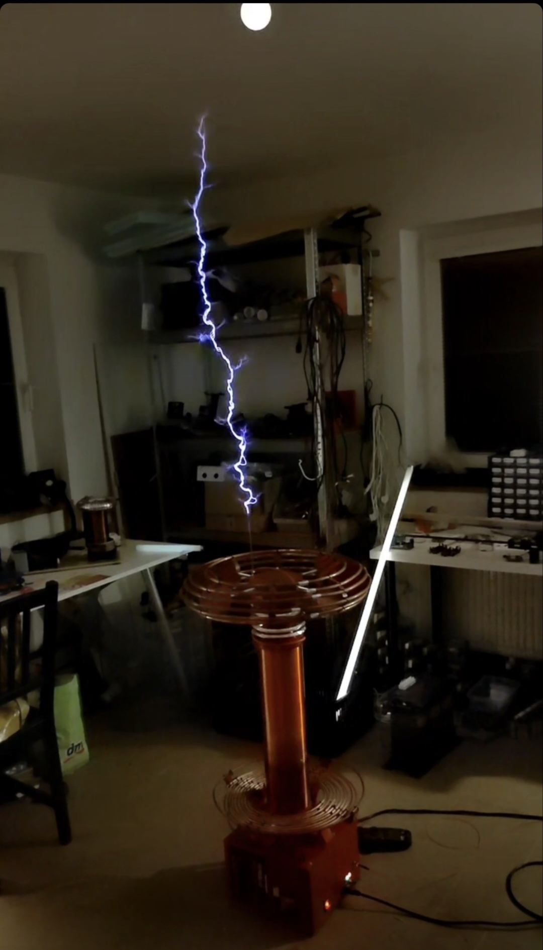
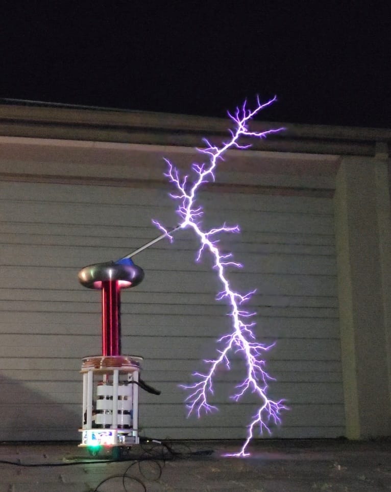
The weather kept it indoors, so this was not full power. At about 180 V AC and 200 µs the discharge reached about 130 cm. The secondary is 45 cm, so that is 2.88 times the winding. It is not finished tuning. It is a good result for a coil that has not been outside yet.
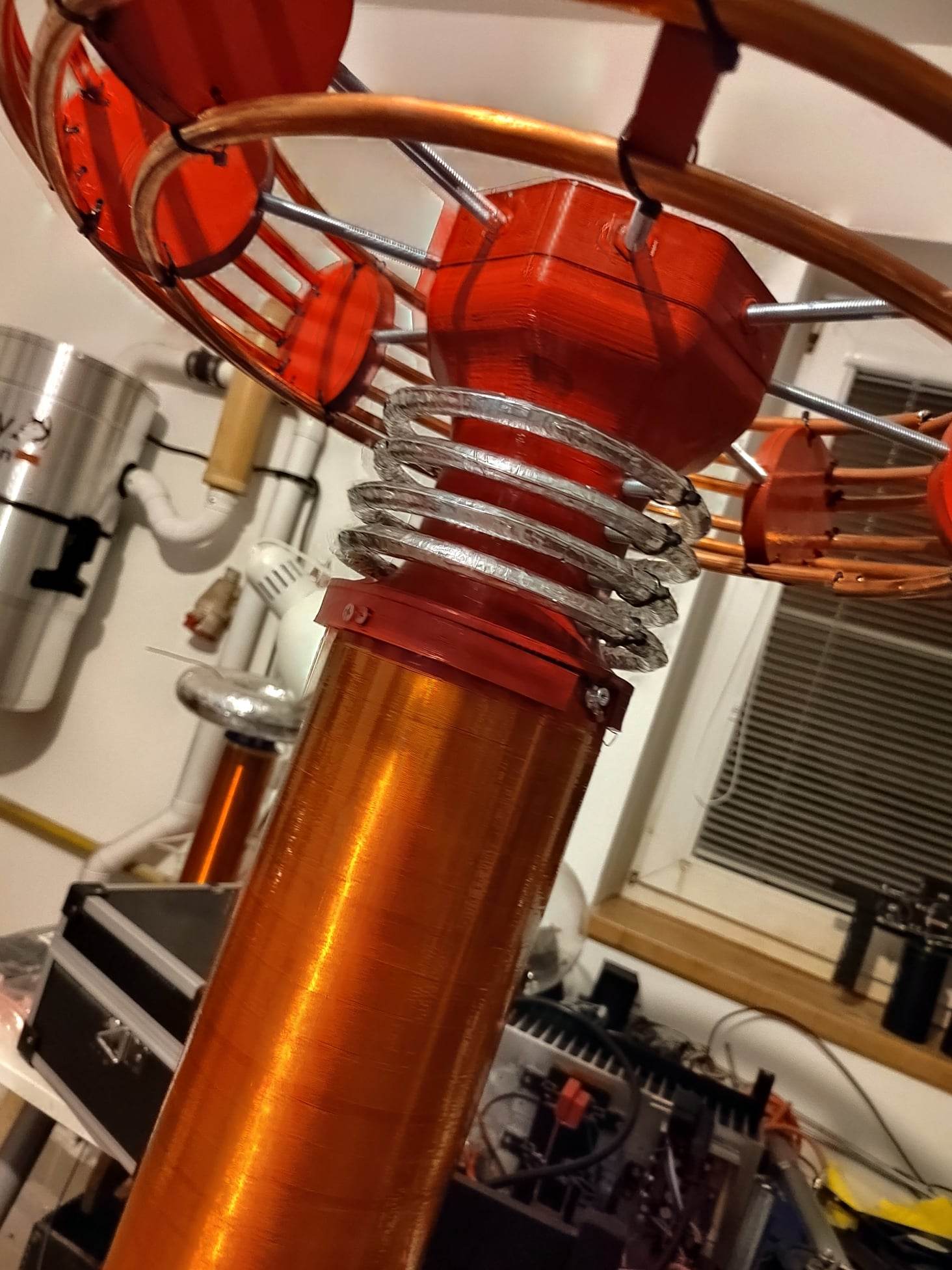
As built
Pulse-skipping used to go past the datasheet, not to hide inside it. The topload is the part that had to be built twice.
Specification
- Bridge: CM150DY-12H. Bus 10 000 µF at 450 V. Snubbers 1 µF at 1.2 kV
- Driver: UD+ with pulse-skipping. LM317 at about 22 V, from an 18 V AC transformer
- MMC: 9S3P Tesla TC343, 150 nF at 1 kV, 50 nF at 9 kV
- Primary: 8 mm copper tube, 37.7 µH, tapped at about 5.5 turns. Tunes to about 117 kHz with the MMC
- Secondary: about 1300 turns of 0.3 mm, 12.5 cm diameter, about 45 cm of winding
- OCD: about 450 A. On-time up to 3 ms, and 200 µs for the 130 cm indoor run
- Topload: 10 mm copper tube on printed spacers, about 102 €
- Streamers: about 130 cm indoors, 2.88 times the secondary, at about 180 V AC