
Project / Finished product
ZVS driver
Two spare STE40NK90ZD MOSFETs, three 1 µF tank capacitors and a coil of 8 mm copper tube — an induction heater built from parts already on the bench, then given a soft start and an on/off switch.
- Power electronics
- Status
- Finished product
- Devices
- STE40NK90ZD
- Tank
- 3 × 1 µF · 1200 V
- Coil
- 8 mm copper tube
- Frequency
- ~50.6 kHz
At a glance
Introduction
For quite some time I had two spare STE40NK90ZD MOSFETs and no particular job for them. An induction heater built around a ZVS oscillator was the obvious use: it is satisfying to heat metal until it glows, and most of the power parts were already on the shelf. Three 1 µF 1200 V MPAPB1K2W10J0M6 capacitors, rated 25 A RMS, and a work coil wound from 8 mm copper tube. Nothing new had to be bought.
Most ZVS drivers also need a very stiff supply just to start. I wanted this one to charge the bus capacitors first and only then begin oscillating, and I wanted a button to start and stop it without cutting the supply every time.
How a ZVS driver oscillates
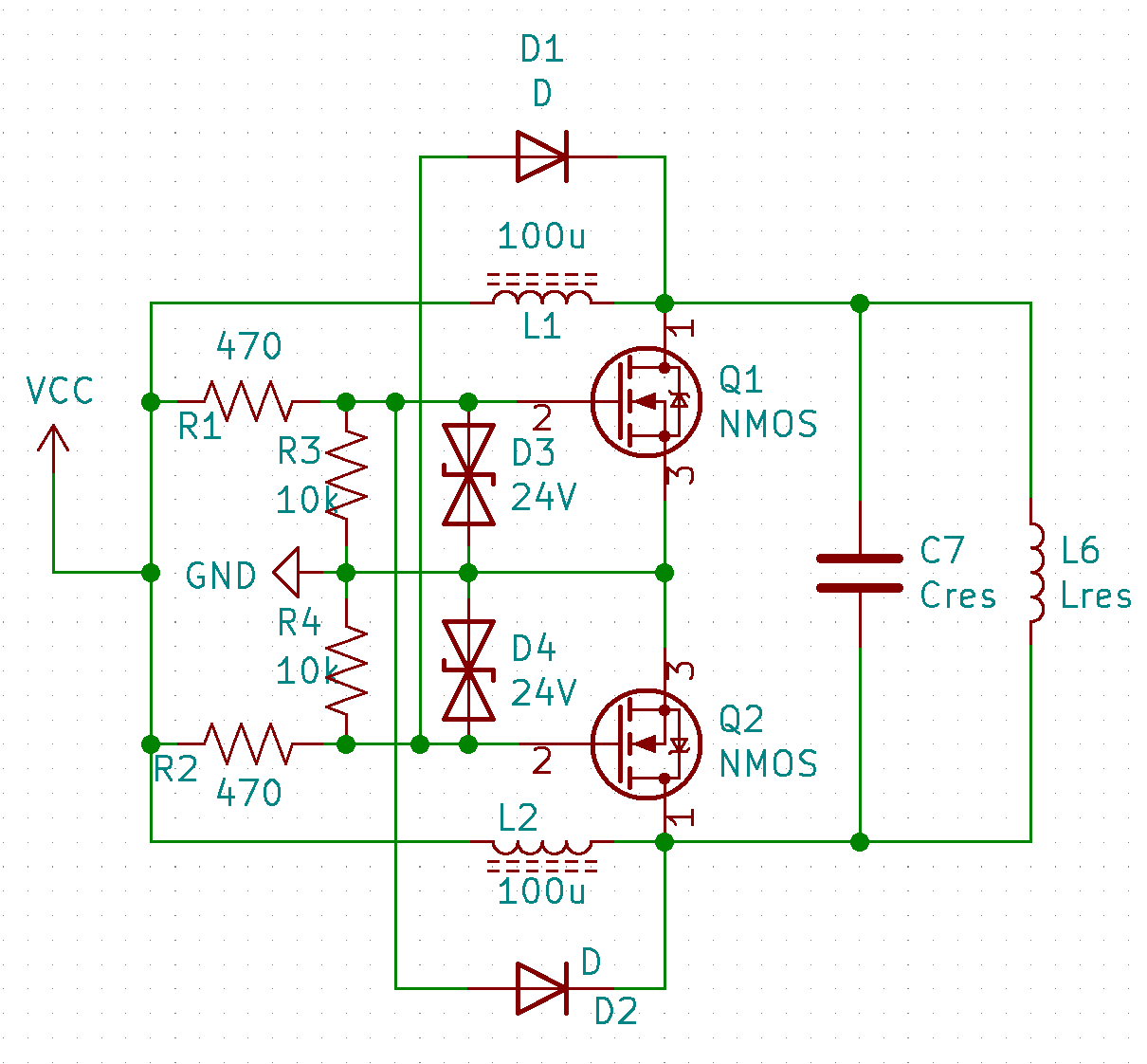
The circuit in the figure above is the whole power stage. In principle it is 14 parts. Drop R3, R4, D3 and D4 and a careful build can run on 10. It will still push several hundred watts through the work coil.
Oscillation starts from the mismatch between R1 and R2. Real resistors are never equal, so one gate — say Q1 — reaches threshold first and that MOSFET turns on. Its drain collapses, D1 conducts, and D1 pulls Q2’s gate down so Q2 stays off. The resonant capacitor then discharges through Q1. Once that voltage falls below the point where D2 can conduct, D2 pulls Q1’s gate down, Q1 turns off, and Q2 is free to charge up and take the next half-cycle. The two devices keep shutting each other off through D1 and D2.
Meanwhile the supply keeps topping up the tank, and the tank dumps that energy through Q1 and Q2. A large resonant current builds in the work coil. L1 and L2 set how much power gets in, and they keep the tank’s AC voltage out of the supply.
The tank runs at its resonant frequency. Electroboom’s walkthrough of the same circuit is worth watching before building one: youtube.com/watch?v=hFJeIt_JcEc
f0 = 1 / (2 π √(L1 · C1))
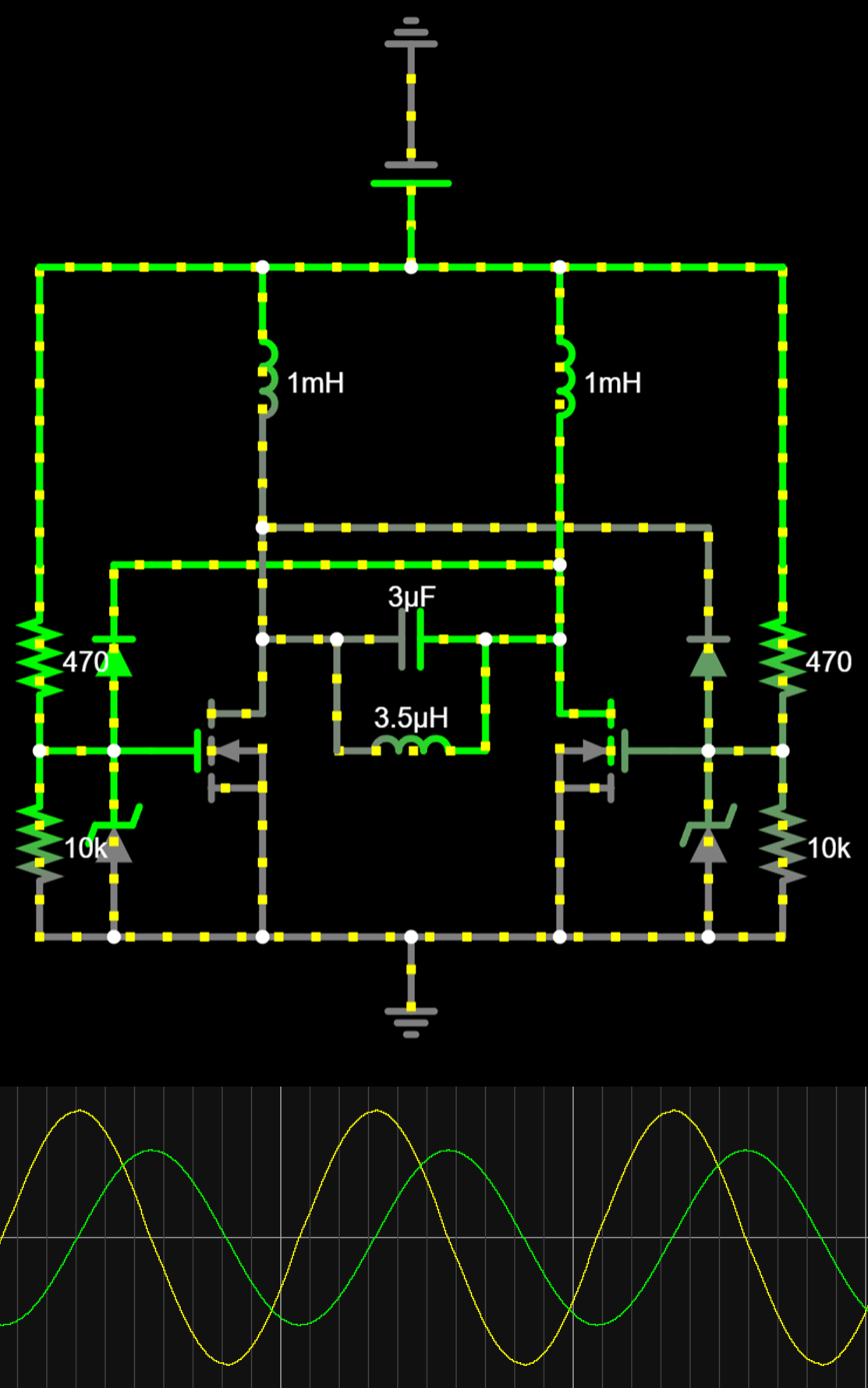
A quick simulation
The same circuit drops straight into LTspice, or into Falstad if you want to watch the gates and the tank move.
Why this is not the inverter you ship
It is efficient where it counts: the MOSFETs switch while the voltage on their drains is near zero. The waste shows up somewhere else. R1 and R2 have to charge the gates at tens of kilohertz and also feed D1 and D2, so they burn real power. Once the drains rise above the zener voltage of D3 and D4, those same resistors act as droppers.
Resonance also multiplies the input voltage. The drains see about π times Vin. At 30 V in, the peaks are already near 100 V. On rectified mains, about 325 V, they climb past 1000 V. A 1200 V transistor does not save you: the inrush and the turn-on transients will kill the circuit anyway.
It is an inverter for getting something hot on the bench. It will usually run with ordinary transistors and a low input voltage, which is also why the supply side is the less dangerous part. It is not an industrial stage. There is no frequency control, you cannot turn it off without removing power, and I would not call it reliable. If you need control, build something with a gate driver and a microcontroller. The simplicity is still hard to resist, so I built it.
Advantages
- Simplicity
- Efficiency
- Low cost
- High power
Disadvantages
- No frequency control
- Impractical at high input voltage
- Very high inrush
- High input power with no load
First build
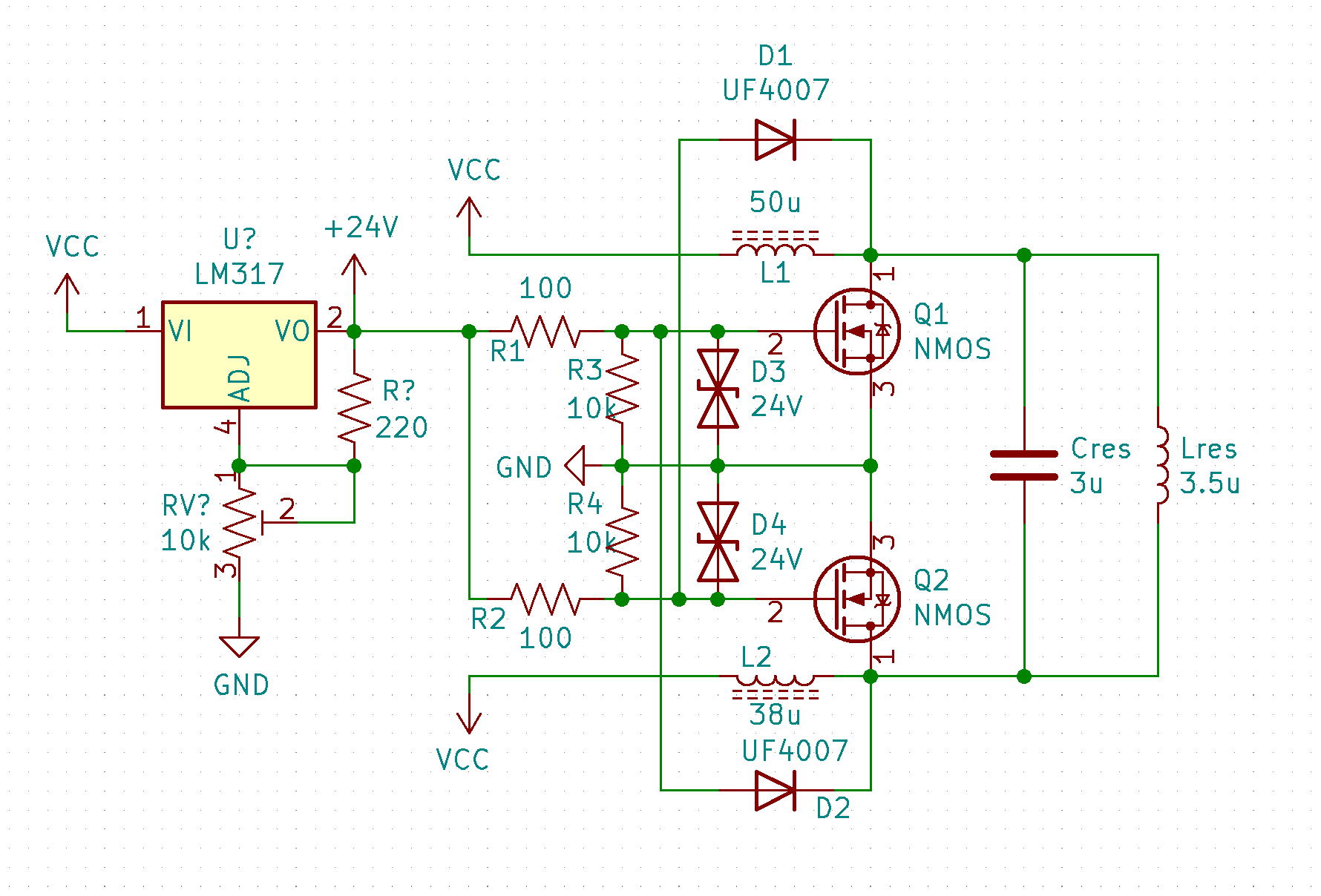
The transistors went on a heatsink, the tank capacitors were soldered straight to the work coil, and the rest of the circuit grew around that. The first schematic is the basic oscillator with a few changes.
Gate resistors that melt solder
These MOSFETs have about 25 nF of gate capacitance each, roughly ten times an IRFP250N. A 470 Ω resistor into 25 nF is an 11.75 µs time constant. The tank was near 50.6 kHz, so a cycle is only 19 µs. The gates would spend more than half of every cycle climbing through the linear region.
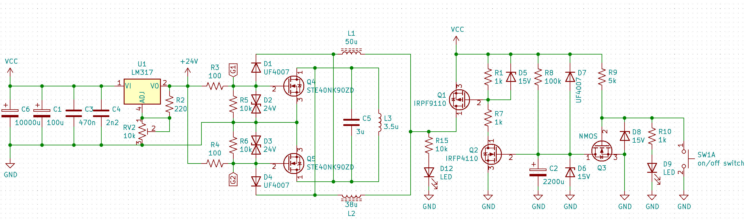
With 100 Ω the time constant drops to 2.5 µs. Still slow, but usable — and the resistors then pass a lot more current. At 33 V input the solder on them started to melt. A linear regulator, an LM317 set to 24 V, now feeds those resistors. They still run hot, but they no longer smoke. The regulator is linear and still dissipates the power; it just does it in a TO-220 package that can sit on the heatsink. A resistor cannot.
Winding L1 and L2 cost one ferrite core. It rolled off the bench and cracked, which lowered its permeability, so the two inductors were no longer matched. I left it. It ran fine.
A start-up circuit that fought the supply
The first build had no input capacitors of its own. It borrowed the ones in the power supply. A ZVS stage wants a large current to start, and local bus capacitors swallow that current while the voltage rises slowly, so the oscillator never kicks. The fix is to charge the bus first, then release the stage.
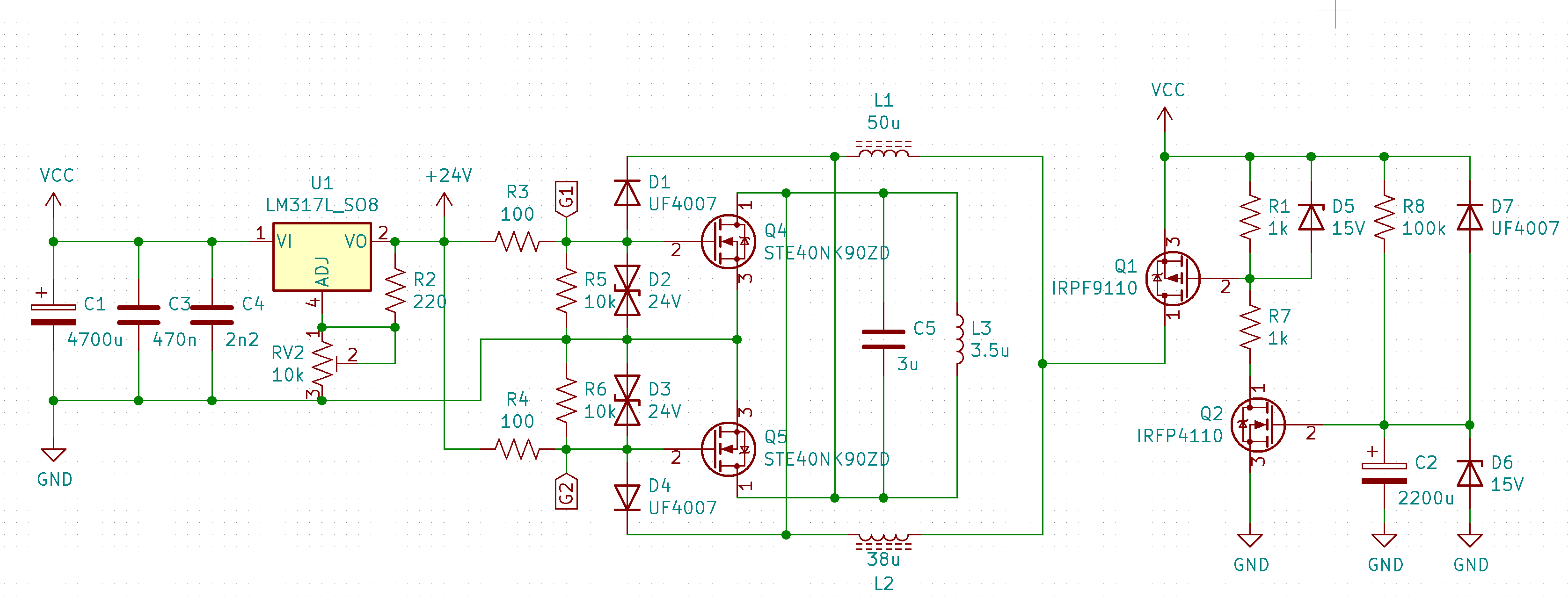
The first version of that idea clamped the power-MOSFET gates with two small transistors. After about half a second a timing capacitor let another transistor release the clamp. Zeners protected the gates and also limited the voltage on the timing capacitor, so it could stay small. The circuit does what it was drawn to do. It still has a fatal order problem, which is why this schematic did not stay.
The gates have to be alive first
The ZVS gates must already be powered before voltage reaches the drains. I did not know that until David Knierim pointed it out on highvoltageforum.com. The simple oscillator was getting less simple, and the start-up path had to be thrown out.
Switch the bus, not the gates
Leave the gates biased and switch the current into L1 and L2 instead. Hold the bus off until the input capacitors are charged, then connect it as quickly as possible.
A relay looks perfect. Power its coil from the LM317 and a 24 V relay closes only once the bus is at least a couple of volts above 24 V, which is already enough to start. No separate timer. Relays are slow, though. The contacts arc for several microseconds before they are really closed, and during that time the stage is starved of current and does not oscillate. The other problem is inrush. No-load input current here was about 1.7 A, and the inrush can be a hundred times that. A relay that survives it is an expensive relay.
P-channel MOSFETs can do the same high-side switch. I had a pile of IRFP9110s. They are not ideal: 0.2 Ω on, so 20 A is 80 W in one device. Four of them in parallel, on a heatsink, share that down to about 20 W at 20 A. Not elegant. A P-channel IGBT would have been kinder. Four FETs were what was in the drawer.
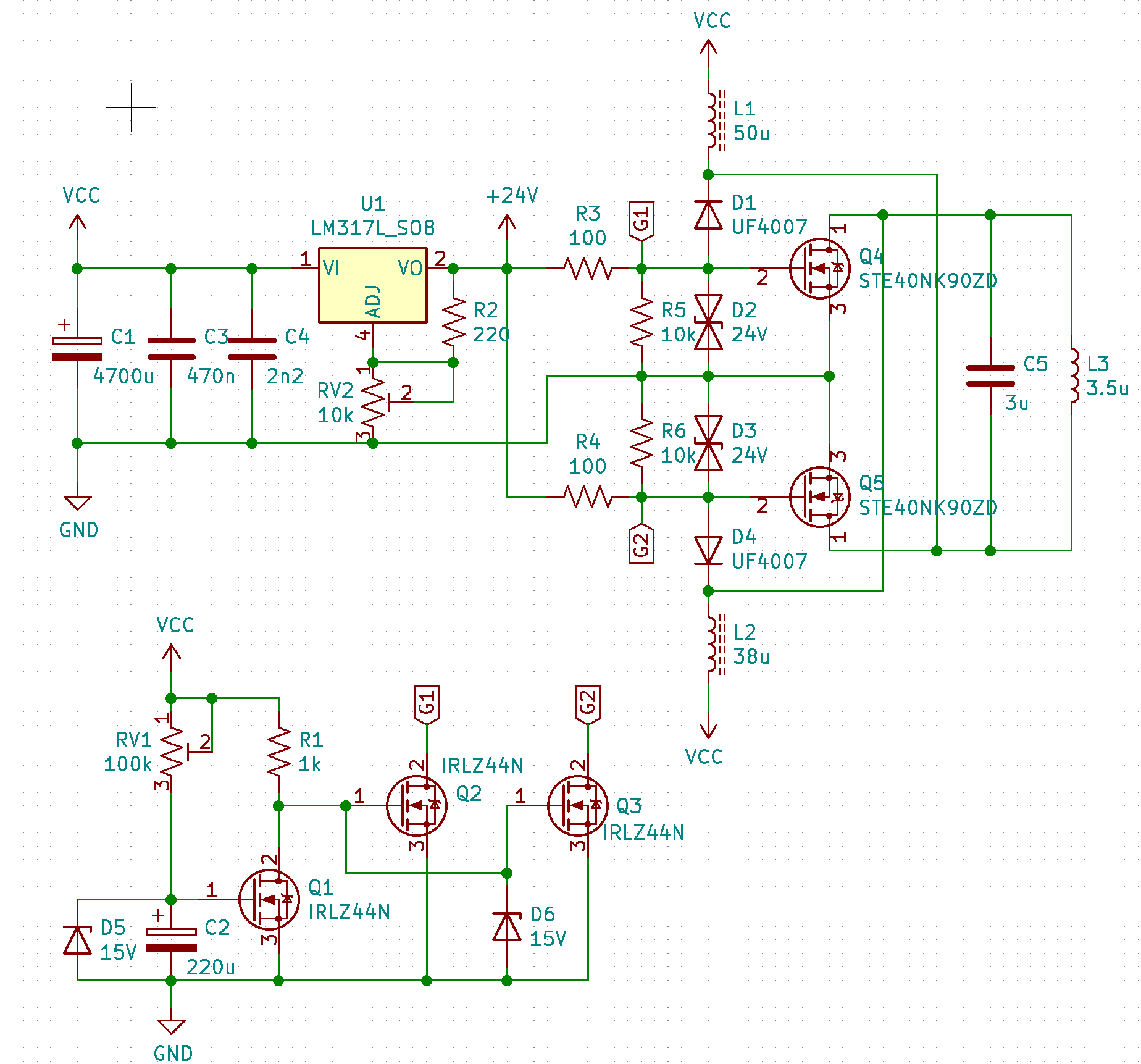
Start-up that actually starts
The timing is the same idea as before, moved to the high side. C2 charges through R8 until Q2 turns on and pulls the gate of the P-channel switch down, which turns that switch on. D5 and D6 clamp the gates. R7 limits current in D5. D7 discharges C2 whenever the supply collapses, so the next power-up has to charge the timer from zero again. A resistor in series with D7 would be kinder — as drawn, turn-off dumps a 2200 µF capacitor straight through that diode.
More bus capacitance
Fed from stepped-down mains through a half-bridge rectifier, the bus is recharged at 100 Hz. At more than 20 A of load, a small capacitor sags too far to keep the oscillator running.
42 V of ripple is too much. The bus would have to sit at 70 V or more just to stay above the voltage the stage needs at the bottom of the ripple. I was aiming for 50–60 V, so the original capacitor had to go. A 100 µF part sits next to the transistors, and a 10 000 µF capacitor sits beside the board. Ripple should land under 20 V. Still not pretty, and it is the usual tax of a low-voltage, high-current tank: the capacitors grow faster than the power does.
Uripple = I / (f · C) = 20 A / (100 Hz · 4700 µF) = 42 V
A button, and eight transistors
One more transistor. By April 2023 the count had gone from two devices to eight. Pulling Q3’s gate down with the button pulls down Q2, which lets the P-channel gate rise and opens the high-side switch. Press to run, press to stop. Two LEDs show the state of the circuit.
The work coil was water-cooled after this. Without it the copper tube climbed past 200 °C.
Where it stopped being worth it
The useful thing about a ZVS driver is that it is small and obvious. Adding a power switch turned that into several parallel P-channel MOSFETs, a timer and a regulator. The tank also wants low voltage and very high current, and a supply that can do both is not a casual bench part.
It still worked, up to a point. At high load the N-channel devices carry enough current that their on-state voltage rises. When that voltage exceeds the threshold of the opposite MOSFET, both conduct, the oscillation collapses, and the stage is a short. I hit that at about 40 A of switch current. Every transistor survived. IGBTs would hold a flatter on-state voltage, and there is a published fix from Jakub Tejiščák for this exact failure. Either one adds more parts to a circuit that has already left the handful-of-components idea behind. For a high-power induction heater I would pick a different topology.
I would still tell someone new to power electronics to build a ZVS stage. Done carefully it is cheap, it will make 700 W and more, and it is a clear demonstration of soft switching and of what a resonant tank will do. This one was taken apart before a full-power run was filmed. The only recording left is a low-power pass, under 400 W, heating a small nail.